KBC Networks WES User Manual
Page 8
Wireless Ethernet PtP & MP System Operations Manual
WES CONNECTION DIAGRAMS
The following wiring schemes represent the configurations that have been tested and
verified by KBC based on typical Ethernet wiring solutions. Other wiring configurations
could be possible based on the application. A bench test is recommended to verify the
designs below.
POINT TO POINT SYSTEM
IP Camera
NVR
Client
Host
MULTIPOINT SYSTEM
Client
MP Host
Client
* Type of Cat5 configuration may be determined by LAN port of the Ethernet device.
If the port is a 10/100 port, you may require a crossover cable. Most cables used
to the connect the WES system are configured using a straight-through color
code.
6
Wireless Ethernet PtP & MP System Operations Manual
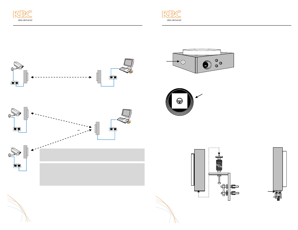
WEM INSTALLATION & OPERATION
A. SELECT CHANNEL
1. Remove the ½ inch plastic cap on the side of the Host/Client.
2. The rotary switch inside features a small black arrow pointing at the
selected channel indicator. The switch has 8 positions. Channels 0
through 3 are all 5745 MHz. To select a different frequency, select
channel 4 or higher then power cycle the WEM device.
Default set to channel 0 (5745 MHz) as shown in the
diagram to the left.
3. Power cycle device to implement channel change
4. Reseal port by replacing weatherproof plug
B. MOUNT DIRECTIONAL HOST/CLIENT
Mount the Host/Client using the included wall/pole mount bracket and
hardware. Connect the black mounting assembly with adjustment swivel to
mounting L-shaped bracket with the ¼-20 button head screw. Connect the
unit to the mounting assembly using the ¼” mounting hole in the case
(diagram B-1). Position the Host and point it in the direction of the Client (or
Client to Host) and tighten the swivel mount. Lock in the antenna upon a solid
green Signal Level LED (Multipoint Host green LED will flash).
Diagram B-2, above right, shows strain relief weatherproof plug. RJ-45 port
protected when plug in use. Tighten snug to case bottom (section A) but
leave open enough (section B) for slight cable movement and condensation
release.
7
Ethernet
Cat5*
Straight-
through
Straight-through
Ethernet
Cat5*
Ethernet
Cat5*
Straight-
through
Straight-
through
Ethernet
Cat5*
Ethernet
Cat5*
Straight-through
< 90
⁰
FAQ: To which port on the PIM does the WES connect?
The “P+Data Out” always connects to the WEM.
FAQ: How far from the Ethernet device can I mount the
WEM?
The cable from the Ethernet device to the WEM cannot exceed
100 meters (326 feet). The PIM can be situated anywhere along
that 100m length of cable.
0
7
6
4
2
1
3
5
B-1
B-2
A
B