One Systems PT-10 User Manual
Page 14
Advertising
One Systems, Inc. 6204 Gardendale Dr., Nashville, TN 37215
14
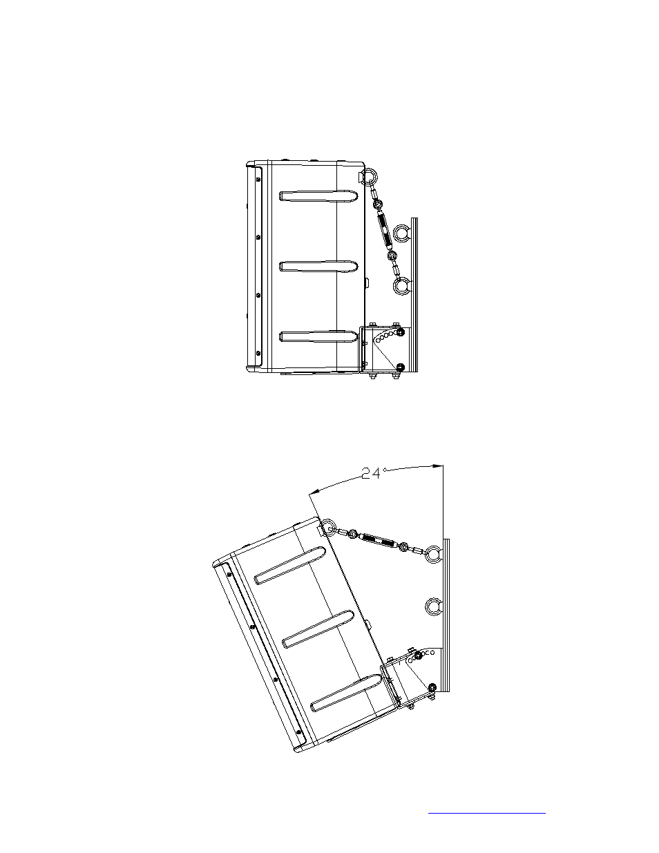
vertical, 24 degrees and 40 degrees using the eyebolt positions shown in Figure 7. Note
that Figure 8a and 8b use the same link and turnbuckle combination but different
eyebolt locations and the Figure 8c uses chain sections as well as the quick links and
the turnbucklel
Figure 8a
Figure 8a represents the Link assembly with the enclosure in a vertical orientation and
the Link using the lower eyebolt position
Advertising