One Systems PT-10 User Manual
Page 9
One Systems, Inc. 6204 Gardendale Dr., Nashville, TN 37215
9
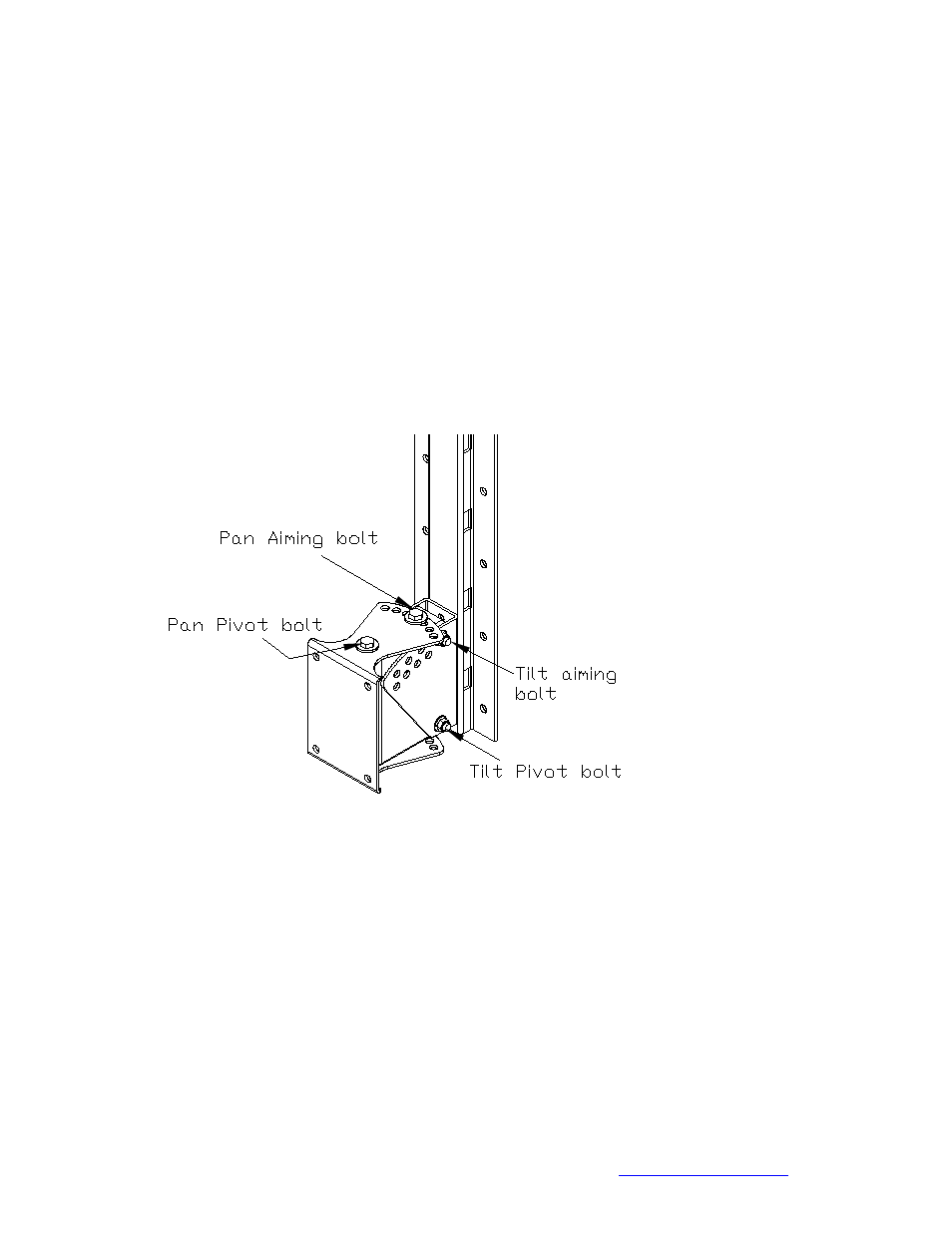
The loudspeaker and loudspeaker section of the bracket may now be joined to the wall
section and the required pan and tilt angles selected. This is a two person job and
extreme care should be exercised to avoid serious injury.
The M10 tilt pivot bolt should be inserted first and secured but not completely tightened
using the nylon insert M10 nuts supplied. The tilt pivot bolt is shown below in Figure 2d.
Then the M10 tilt aiming bolt should be inserted and nylon insert nuts applied. Then the
tilt axis bolts should be tightened.
CAUTION: DO NOT REMOVE THE PAN PIVOT BOLT
Next the pan angle may be adjusted by removing the M10 pan aiming bolt, but NOT the
pan pivot bolt, and setting the desired pan angle and then re inserting the M10 bolt.
Once both the tilt and pan angles are set, make sure that all bolts are tight and secure.
Figure 2d
INSTALLING THE LINK
Figure 3 is a representation of the Link assembly. This assembly MUST be used
whenever the PT-76a, PT-38a or the PT-30 is being used. Each pan and tilt bracket is
supplied with a link assembly.
SEE SECTION 5 OF THIS MANUAL FOR DETAILS ON THE PROPER MOUNTING
OF THE LINK ASSEMBLY!