One Systems PT-10 User Manual
Page 28
One Systems, Inc. 6204 Gardendale Dr., Nashville, TN 37215
28
Figure 8c represents the Link assembly with the enclosure in a 40 degree tilt. The Link
assembly uses the top eyebolt and the stainless steel chain has been added to achieve
the proper tension on the assembly. Notice the “dropped” chain links in Figure 8c.
Warning: If the turnbuckle assembly is turned and the loudspeaker enclosure angle
begins to change (if the down tilt angle begins to move toward 0 degrees vertical then
the turnbuckle has been OVER TIGHTENED. Turn the turnbuckle until the down tilt
angle is set by the M10 thru bolt on the pole bracket and there is slight tension on the
Link assembly.
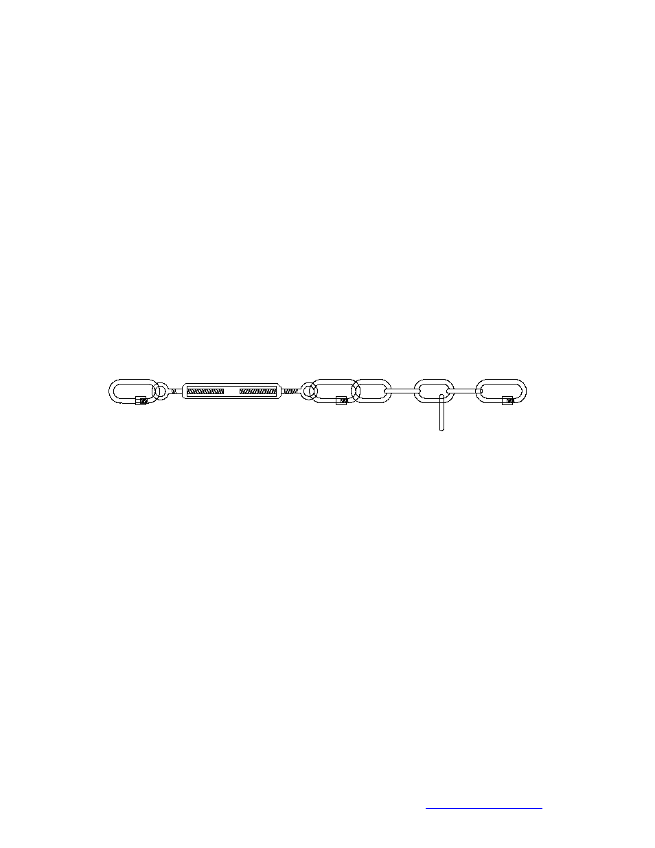
Figure 10 is a close up view of the Link assembly. Certain down tilt angles may require
a link to be “dropped” from the chain as shown below. The lower quick link is positioned
in various chain segments based on the desired degree of down tilt. The turnbuckle
should be adjusted, as described in this section
In any position, the turnbuckle must be adjusted to allow the proper amount of tension
on the Link. The Link should never pull the loudspeaker up towards vertical. The Link
may be configured with or without the chain section and quick link depending on the
down tilt angle of the enclosure.
Figure 10
Secondary safety cables are STRONGLY recommended and should be
secured to a structural point NOT associated with the PT bracket or
loudspeaker. The Link assembly is NOT a secondary safety!