Paxton Superchargers Ford Mustang GT User Manual
Page 22
6-4
P/N: 4809628
©2003 Paxton Automotive
All Rights Reserved, Intl. Copr. Secured
05JUN03 v2.1 MusGT(4809628 v2.1)
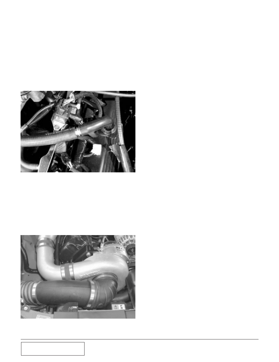
Fig. 6-l
T.
Place the secondary intake tube/bypass
valve assembly on the supercharger inlet,
and attach it to the flex hose. Attach the
other end of the bypass valve to the dis-
charge tube. Connect the hose that was pre-
viously installed on the hard plastic crank
case ventilation line to the brass fitting on
the intake tube. Tighten the clamps. The fin-
ished installation appear as in Fig. 6-m.
Fig. 6-m
Q.
Join the supercharger inlet duct to the previ-
ously installed MAF hose with the supplied
#52 hose clamp.
R.
Connect the opposite ends of each hose to
the crankcase breather fitting on the driver’s
side valve cover (5/8” hose) and the idle air
control resonator (3/x4” hose). Trim hose
length if required.
S.
Install the 5/8” hose union into the
crankcase breather line. It may be necessary
to trim this line to ensure a proper fit. (See
Fig. 6-l.)