Installation and operation, Wiring diagrams, Nsd safety mat system – Pinnacle Systems NSD User Manual
Page 13
8
Installation and Operation
NSD Safety Mat System
Wiring Diagrams
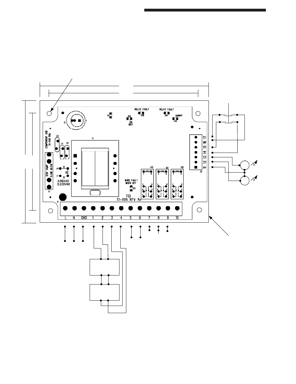
NSD-TR-01 (Metal Box Controller) - Diagram below is for older boards PRIOR to Rev 10.
NOTE: If you daisy chain mats, the blue/white is one
pair and should go to Terminals #1 and #2. The black/
brown is the other and should go to the blue/white pair
of the second mat, and so on. The black/brown pair of
the last mat goes back to Terminals #3 and #4.
If the mat has two lamp cords, then either pair can go
to Terminals #1 and #2 and so on.
NOTE: Canadian market wiring is black, red, red,
black with 18-guage wiring size.
7.0"
6.25"
5.
0"
4.25"
4 mounting holes (#8
screws)
120vac
power
Earth
Ground
Mat #1
Mat #2
Safety Output:
Wire in series
with STOP
circuit.
This is a N.O.
Held Closed
output
NC C NO
Aux Output: for
status only
Test
Power ON
Push “Clear” button to Reset
mat control.
Mat Control will Auto-Reset
is both N.C. contacts are
disconnected.
GRN
RED
External Status
Indicators
24vdc
Indicators on
door are LED’s
with internal
resistors set for
24vdc
Connect either of the 2 wire pairs
to Terminal#1 & #2, and the other
pair to Terminal#3 & #4 (as
shown)
NSD Mat Wiring:
Style “X” or “E”
1 Black, 2 Red, 3 Black, 4 Red
Or Style “W” or “P”
1 Blue, 2 White, 3 Black, 4 Brown
White Steel
mounting plate
is used to
support the PCB
Relay Fault LED’s D14,D18
(ON=good, OFF=Relay stuck on FAULT)
On Mat LED’s D10,D12
(ON=ON mat, OFF=OFF mat)