Installation and operation – Pinnacle Systems NSD User Manual
Page 17
Advertising
12
Installation and Operation
NSD Safety Mat System
NSD-DR-04
(DIN-rail Controller with Diagnostics)
Jumper Settings
1= jumper install
Number of Mats:
JP2 JP1
0 0
1 mat
1 0
2 mats
0 1
3 mats
1 1
4 mats
JP3
1= Manual relay reseting
0= Automatic relay reseting
JP4
1= External relay checking enabled
0= Disabled
JP5
Not used at this time
JP6
Not used at this time
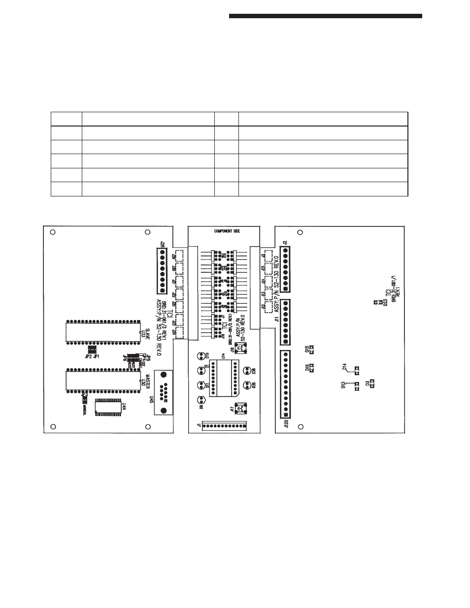
NSD-DR-04 (DIN-rail Controller with diagnostics)
Board Connector Layout
J2,J26 MAT INPUT #1 thru #4
JP1,2 NUMBER OF MATS SELECTION
J1
DIAGNOSTICS DISPLAY (remote)
JP3
MANUAL
J120
POWER/OUTPUT
JP4-6 EXT, AUX1, AUX2
D13,14 Safety relay output on (closed)
D3
+12v supply
D16
Auxiliary relay output on
D1
+5v supply
D15
Fault relay output on (closed)
D23
+20v supply
Advertising