Vectronics VEC-412K User Manual
Page 16
VEC-412K Owner's Manual
Rapid Battery Charger/Conditioner Kit
14
! ! 3. Locate the 1N5822 diode (largest bodied diode in kit). While
observing cathode lead orientation, insert and solder at location D2.
! ! 4. Locate the 1N5223B diode. While observing cathode lead orientation,
insert and solder at location D3.
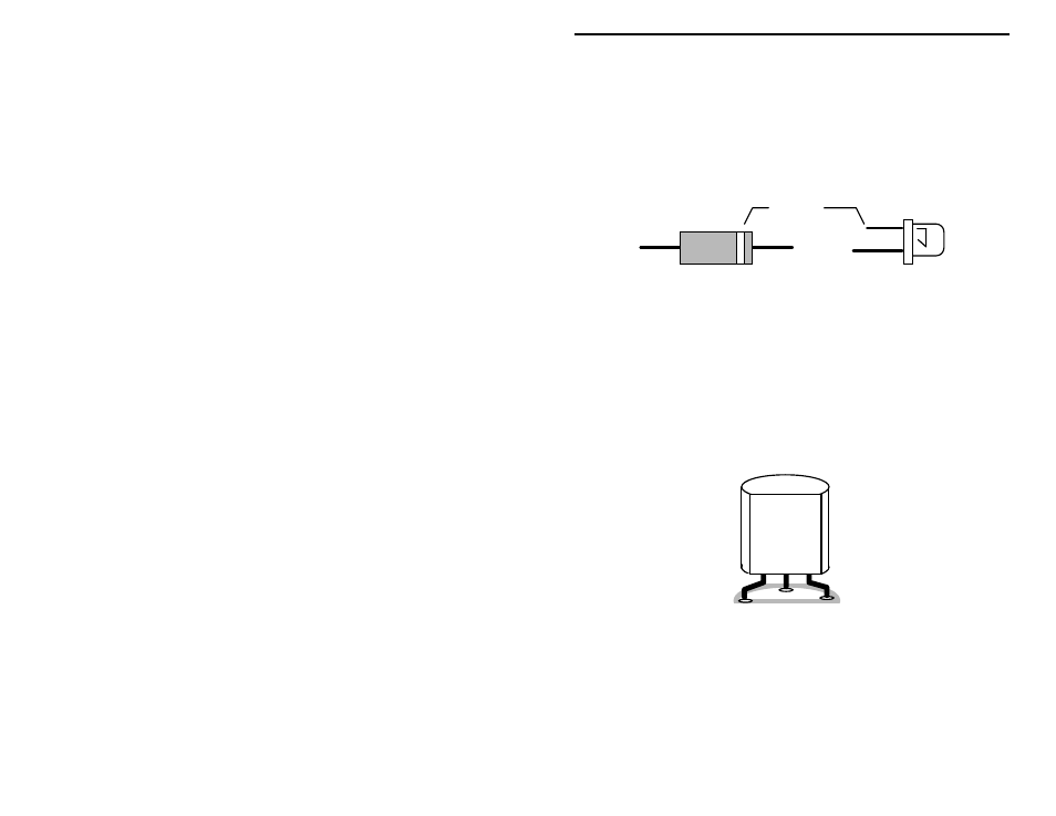
Locate the RED LED. Observe that the cathode lead is the shorter of the two
device leads. The cathode lead is also indicated by a small flat area in the
otherwise round base of the device.
Cathode
Diode
LED
(shorter Lead)
! ! 5. Install the RED LED at location CR1 on the PC board. Verify that the
body outline corresponds to the PC board legend and pictorial
diagram. Install the LED leads until the shouldered stops on the leads
are flush to the PC board. Bend the leads so the LED is flush with the
edge of the PC board. Solder.
! ! 6. Locate the YELLOW LED . Install and solder at location CR2 on the
PC board. Observe polarity.
! ! 7. Locate the 2N3904 transistor. Install and solder at location Q2. Note
the device has a rounded and flat side. Observe proper orientation
using the PC board legend and pictorial diagram.
2N3904
Q2
! ! 8. Locate the 78L05 three-terminal voltage regulator IC. Observing
polarity, install and solder at location U2.