Vectronics VEC-412K User Manual
Page 20
VEC-412K Owner's Manual
Rapid Battery Charger/Conditioner Kit
18
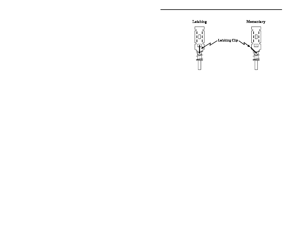
! ! 5. Install and solder the modified momentary-action switch at location
SW4 (make sure the switch body remains level to the board while
soldering).
! ! 6. Locate the 6-position double-pole rotary switch. Hold the switch, and
rotate the shaft fully counterclockwise until the stop is reached. Rotate
the switch clockwise counting the number of positions. There should
be six positions. If not, rotate the shaft back to the fully
counterclockwise position. Remove the mounting nut and lockwasher
on the shaft bushing. This will reveal a second silver colored
indexing-washer. This washer has an pin that corresponds to the
desired stop position number etched on the switch body. If the washer
pin is in a position other than position six, remove the pin, and try
rotating the shaft counterclockwise. It may already be there, or the
index pin may have been setting a false CCW stop. Realign the
indexing washer pin into the proper pin sixth stop-position. Replace
the lockwasher and mounting nut to hold the index washer in position.
The switch should now have six positions.
! ! 7. Rotate the shaft of the 6-position switch fully counterclockwise. The
“flat” of the shaft should now be aligned so it faces the small plastic
post on the switch body.
! ! 8. Install the switch at location SW1—the flat of the shaft and plastic
post should face the rear of the board, that is facing away from SW2
and SW4. Note that all pins of the switch must enter their respective
solder holes. Straighten any bent pins before attempting insertion.
With the switch body mounted flush to the board, solder all pins.
! ! 9. Locate the length of married RED/BLACK zip cable. At one end,
carefully split the wires apart for a length of two inches. Remove ¼”
of insulation from each wire.