Vectronics VEC-412K User Manual
Page 7
VEC-412K Owner's Manual
Rapid Battery Charger/Conditioner Kit
5
Transistors: If transistors are installed incorrectly, damage may result when
power is applied. Transistors in metal cases have a small tab near the emitter
lead to identify correct positioning. Semiconductors housed in small plastic
cases (TO-92) have an easily-identified flat side to identify mounting orientation.
Many specialized diodes and low-current voltage regulators also use this type
packaging. Larger plastic transistors and voltage regulators use a case backed
with a prominent metal tab to dissipate heat (T-220). Here orientation is
indicated by the positioning of the cooling tab.
Emitter
Flat Side
Metal Tab
Metal Can Device
Plastic Device
Tab-cooled Device
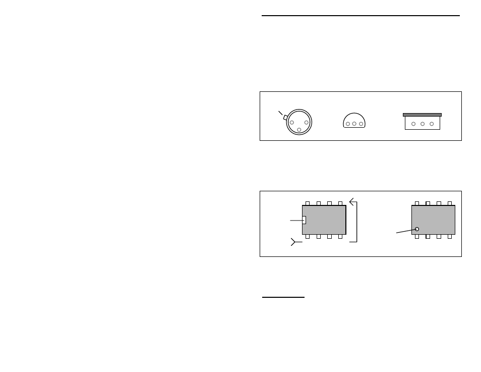
Integrated Circuits: Proper IC positioning is indicated by a dot or square
marking located on one end of the device. A corresponding mark will be silk-
screened on the PC board and printed on the kit's parts-placement diagram. To
identify specific IC pin numbers for testing purposes, see the diagram below.
Pin numbers always start at the keyed end of the case and progress counter-
clockwise around the device, as shown:
1 2 3 4
8 7 6 5
Installation
Key
Key
Installation
Pin Numbers
PARTS LIST
Your package kit should contain all of the parts listed below. Please go through
the parts bag to identify and inventory each item on the checklist before you start
building. If any parts are missing or damaged, refer to the warranty section of
this manual for replacement instructions. If you can't positively identify an
unfamiliar item in the bag on the basis of the information given, set it aside until