AMETEK i Series User Manual
Page 115
Advertising
User Manual
i Series / iX Series
101
5. Principle of Operation
5.1 General
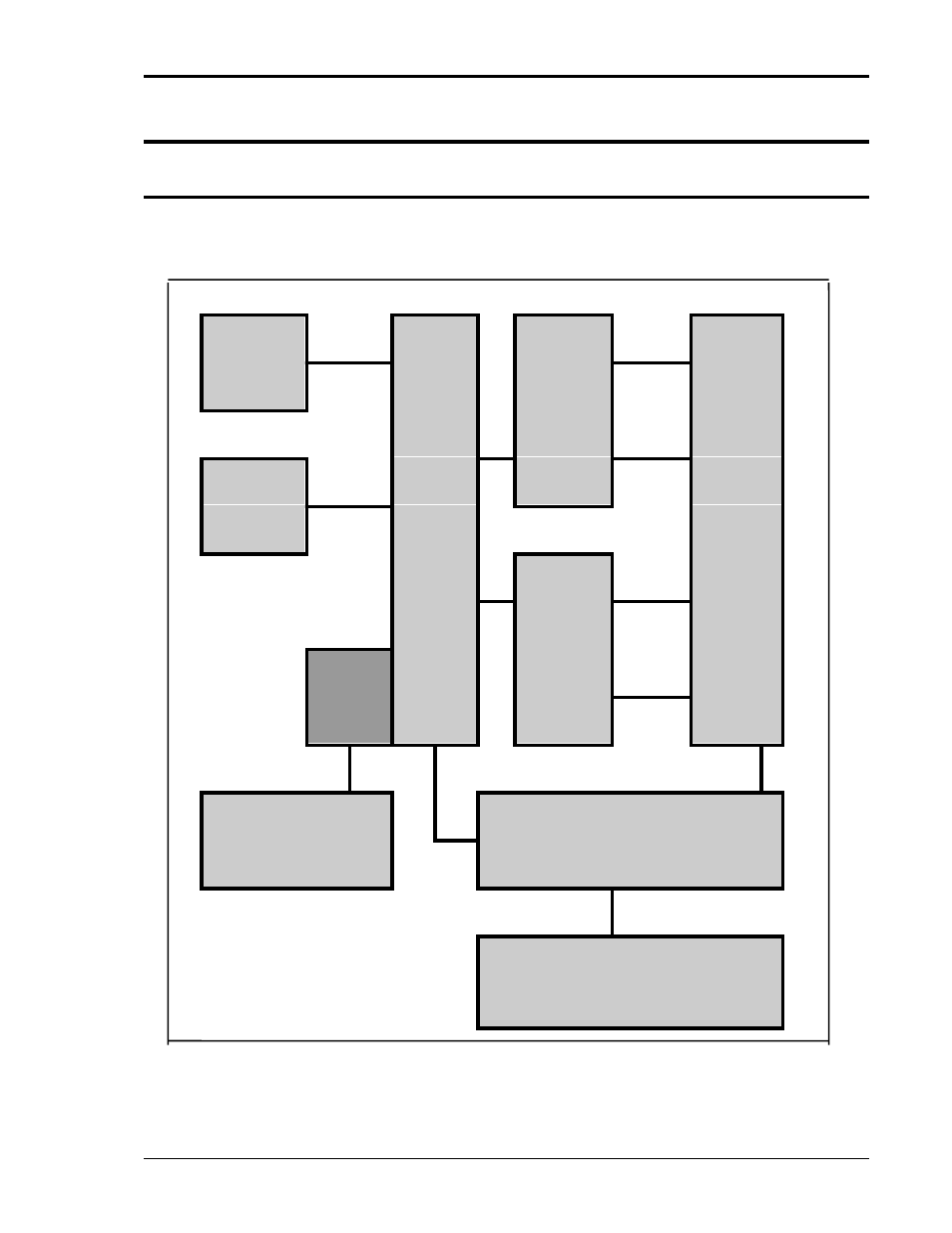
An explanation of the circuits in the 3001iX and 5001iX is given in this section. Refer to Figure
5-1 for a block diagram of the system. Figure 5-2 shows the system interconnect.
OUTPUT
AC
CHOKE
POWER
BOARD
AC
BULK
I/O
CAPS.
LOGIC
BOARD
DC
POWER
BOARD
BRIDGE
BOARD
RECT
CUR
LIMIT
BOARD
3 PHASE
INPUT
OSC
ASSY.
Figure 5-1: AC Power System Block Diagram
Advertising
This manual is related to the following products: