Shaft lock (option) -9, Figure 3-11. shaft lock -9, Shaft lock (option) – AMETEK SGA Series User Manual
Page 59
Sorensen SGA Series
Operation
M550129-01 Rev AG
3-9
3.2
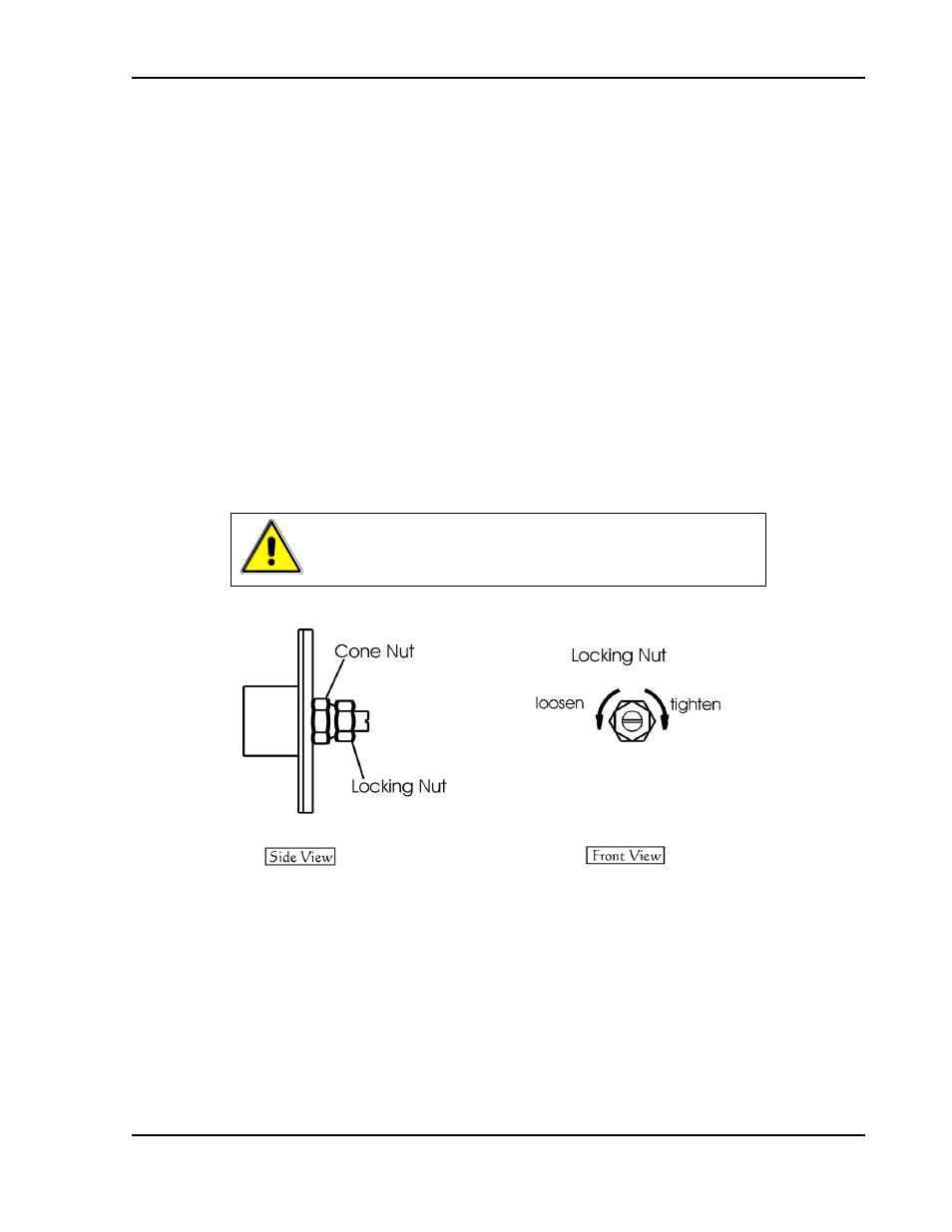
SHAFT LOCK (OPTION)
This option replaces the standard control knobs with a two-piece shaft lock.
These are installed over the voltage and current adjustment potentiometer
shafts to prevent rotating under conditions of shock, vibration, or accidental
contact. For adjustment, the following steps apply:
Loosen the shaft by rotating the outer locking nut counter-clockwise
with a 7/16
” wrench.
Adjust the shaft with a flat screwdriver to the desired output level.
Tighten the outer locking nut, rotating clockwise, to approximately
5 in-lb (0.56 N-m).
Note:
Take care not to over-torque the outer nut. Should the cone nut
become loose or jammed with the outer locking nut, re-torque the cone nut
with a
1/2” wrench to approximately 15 in-lb (1.69 N-m).
CAUTION!
Never fully loosen the cone nut, or remove the shaft lock
from the chassis.
Figure 3-11. Shaft Lock