3 program bus inserts, 4 program master fader – API Audio THE BOX User Manual
Page 46
API “The BOX”
Operator’s Manual
46
5.3 Program Bus Inserts
The program bus is equipped with a stereo balanced insert with switch.
The program insert sends are fed pre-fader immediately after the PROGRAM SUM
INPUTS and compressors and are always active.
The program insert returns are located before the master fader and are routed to the
signal path only when the PGM INSERT switch is engaged.
Rear Panel Program Insert Connections
The program bus insert sends and returns are balanced, low-impedance, line-level
signals routed via ¼” tip-ring-sleeve jacks on the rear panel.
The insert send is located after the compressors on the left and right program buses.
5.4 Program Master Fader
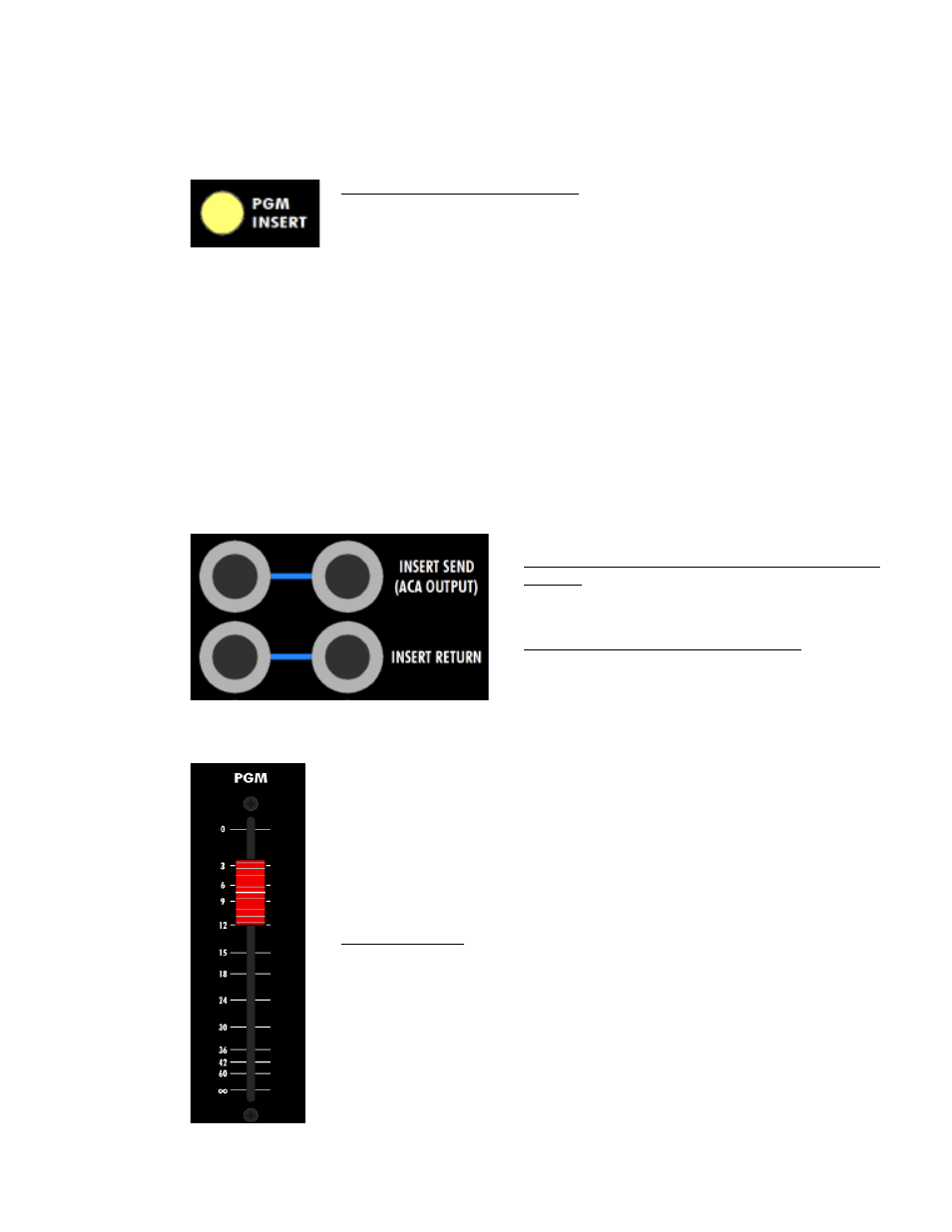
PGM INSERT (program insert): Routes the program insert return to the
signal path
•
The program insert return is active only when the PGM INSERT
switch is engaged
•
Illuminates when engaged
INSERT SEND (ACA OUTPUT) (LEFT &
RIGHT): ¼” tip-ring-sleeve, balanced, low-
impedance, line-level
INSERT RETURN (LEFT & RIGHT): ¼” tip-
ring-sleeve, balanced, low-impedance, line-
level
The fader with the red fader cap below the master section is the
stereo program master fader. The master fader handles the left and
right program bus audio on a single stereo fader.
The master fader is located post-insert. It controls the primary
console stereo program output level and is routed directly to the
PROGRAM BUS OUTPUT connectors on the rear panel.
MASTER FADER: Primary stereo output level control
•
100mm full-size audio-taper fader
•
-∞dB to 0dB range
•
0dB is unity gain
•
Red fader cap