Front panel, Tm722a/b/s front panel, Tm722g front panel – ARRIS TM722G-CT User Guide User Manual
Page 21: Tm722g ext, Tm722g maximum batter, Installing and connecting
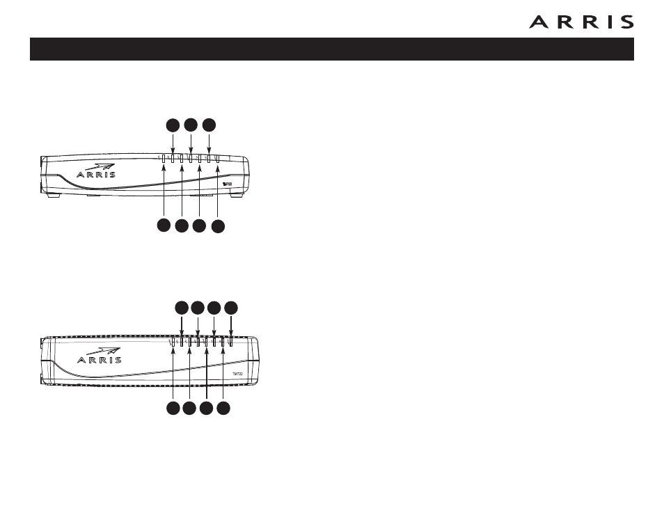
Front Panel
TM722A/B/S Front Panel
The front of the Telephony Modem provides the following indicators.
A Telephone 2: indicates status of line 2.
B Telephone 1: indicates status of line 1.
C Link: indicates Ethernet or USB (if equipped) connectivity between the Tele-
phony Modem and computer. It may be red or green to indicate the con-
nection speed.
D Online: indicates internet data transmission status.
E US: indicates upstream connectivity. It may be red or green to indicate the
connection speed.
F DS: indicates downstream connectivity. It may be red or green to indicate
the connection speed.
G Power: indicates whether AC power is available to the unit.
TM722G Front Panel
The front of the Telephony Modem provides the following indicators.
A Battery: indicates battery status.
B Telephone 2: indicates status of line 2.
C Telephone 1: indicates status of line 1.
D Link: indicates Ethernet or USB (if equipped) connectivity between the Tele-
phony Modem and computer. It may be red or green to indicate the con-
nection speed.
E Online: indicates internet data transmission status.
F US: indicates upstream connectivity. It may be red or green to indicate the
connection speed.
G DS: indicates downstream connectivity. It may be red or green to indicate
the connection speed.
H Power: indicates whether AC power is available to the unit.
Touchstone TM722 Telephony Modem User’s Guide
21
A
B
C
D
E
F
G
H
TM722G
A
B
C
D
E
F
G
TM722A/B/S