3 blade layout, Figure 2-2, Atca-7480 blade layout – Artesyn ATCA-7480 Installation and Use (February 2015) User Manual
Page 50: Hardware preparation and installation
Advertising
Hardware Preparation and Installation
ATCA-7480 Installation and Use (6806800T17A)
50
2.3
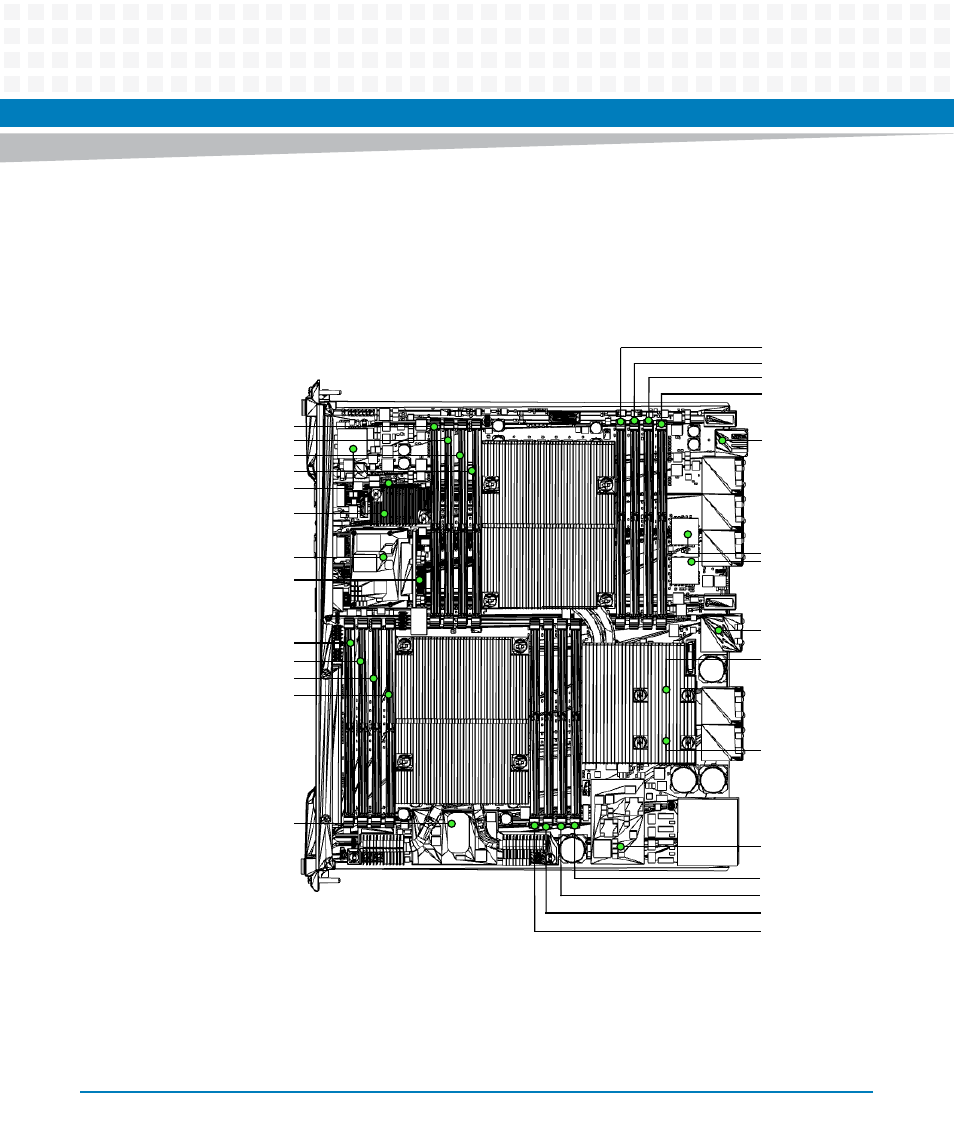
Blade Layout
The following figure shows the location of components on the ATCA-7480:
Figure 2-2
ATCA-7480 Blade Layout
FPGA
Z
O
NE 3
P30
P31
P30
P32
P22
P20
P23
ZONE 1
J21 DIMM 1
J22 DIMM 2
J23 DIMM 3
J24 DIMM 4
Intel C612 PCH
(Wellsburg)
Intel i350
Powerville
MO-297 Carrier
48V to 12V DCDC
J15 DIMM 5
J16 DIMM 6
J17 DIMM 7
J18 DIMM 8
J14 DIMM 4
J13 DIMM 3
J12 DIMM 2
J11 DIMM 1
J11 DIMM 1
ATCA PIM
Intel XL710 #1
(Forteville)
Zone 2
(Base- and Fabric-IF)
Intel XL710 #2
(Forteville)
Zone 2
(Update Channel)
PCIe Gen3 Retimer
RTM 12V Power
J25 DIMM 5
J26 DIMM 6
J27 DIMM 7
J28 DIMM 8
Advertising
This manual is related to the following products: