Table 3-3, Signal segment pinout, Table 3-4 – Artesyn ATCA-7480 Installation and Use (February 2015) User Manual
Page 72: Power segment pinout, Figure 3-6, Mo297 ssd module carrier connector pinout, Controls, indicators, and connectors
Advertising
Controls, Indicators, and Connectors
ATCA-7480 Installation and Use (6806800T17A)
72
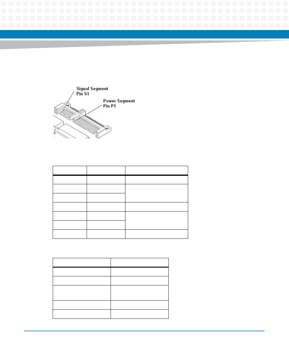
The pinout of this connector is illustrated in the following figure.
Figure 3-6
MO297 SSD Module Carrier Connector Pinout
Table 3-3 Signal Segment Pinout
Pin Number
Function
Description
S1
GND
2
nd
mate
S2
A+
Differential singal Pair A
S3
A-
S4
GND
2
nd
mate
S5
B-
Differential signal Pair B
S6
B+
S7
GND
2
nd
mate
Table 3-4 Power Segment Pinout
Pin Number
Function
P1
Not used (3.3V)
P2
Not used (3.3V)
P3
Not used (3.3V Pre-
Charge)
P4
GND
P5
GND
Advertising
This manual is related to the following products: