B.10.5 dsp configuration, Table b-6, Dsp control signals – Artesyn PCIE-8120 Installation and Use (July 2014) User Manual
Page 78: Pcie-8120 hardware description
PCIE-8120 Hardware Description
PCIE-8120 Installation and Use (6806800R89C)
78
The boot process uses a default device configuration determined by either a lowest common
capability and/or the BOOT_MODE to load a boot image. The final device configuration
information is obtained from the boot image and can override the one used for the boot
process.
The PCIE-8120 card is configured for BOOTP on EMAC 2 on SERDES 2 (SGMII, 1Gbps).
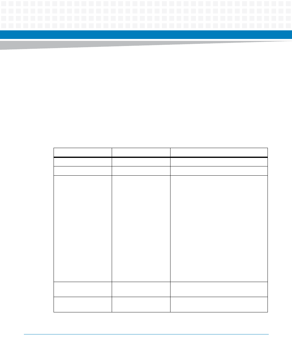
B.10.5 DSP Configuration
The following table lists the assignment of the DSP control and configuration pins:
Table B-6 DSP Control Signals
Signal Group
Controlled by
Description
DSPx_RST_N
CPLD
Reset input to each DSP
DSPx_INT_N
CPLD
Interrupt output from each DSP
DSPx_USER_HW_CONF[
3:0]
HW Strapping
DSP position on Mezzanine set by strapping
resistors range 0 - 11
0000 = DSP0
0001 = DSP1
0010 = DSP2
0011 = DSP3
0100 = DSP4
0101 = DSP5
0110 = DSP6
0111 = DSP7
1000 = DSP8
1001 = DSP9
1010 = DSP10
1011 = DSP11
DSPx_USER_HW_CONF[
7:4]
BASE_ID[3:0]
A card specific 4bit Base ID can be
programmed via the CPLD
DSPx_USER_HW_CONF[
13:8]
HW Strapping
Strapped by resistor to 1