Cv controller, Auto-zone cv & cv-ex 2-8 installation and wiring – Auto-Zone Control Systems Auto-Zone CV & CV-EX Systems Installation & Operation (Version 01C) User Manual
Page 20
Section 2
Auto-Zone CV & CV-EX
2-8
Installation and Wiring
CV Controller
The CV Controller (Constant Volume Controller) may be installed in any convenient
protected location. Observe the recommended environmental limitations for the CV
Controller. It should not be mounted in locations subject to extreme low or high
temperatures (below 20° F or above 140° F) or in damp or wet environments (maximum
of 90% RH). If it is to be mounted outdoors, it must be enclosed in a weather-tight
enclosure.
The CV Controller may be mounted without removing the controller from the mounting
plate. The unit is mounted by securing four (4) screws through the mounting holes in the
mounting backplate. Select the correct screws or other fasteners for the type of mounting
material being utilized.
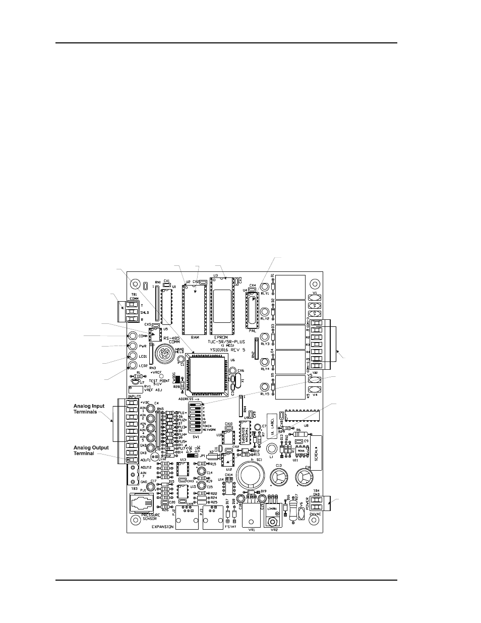
Relay Outputs
Terminals
Diagnostic Blink
Code LED 1
Diagnostic Blink
Code LED 2
RS-485
Communications
Terminal Block
CPU
Chip
Typical
Pin 1
Indicator
RAM
Chip
EPROM
Chip
PAL
Chip
RS-485
Communications
Driver Chip
Real Time
Clock Chip
Communications
LED
Address Switch
Power LED
24 VAC
Power Input
Terminal
Figure 2-5:
CV Controller with Backplate - Components