Auto-Zone Control Systems Auto-Zone CV & CV-EX Systems Installation & Operation (Version 01C) User Manual
Page 25
Auto-Zone CV & CV-EX
Section
2
Installation and Wiring
2-13
Tip:
Be careful when cutting the hole for the sensor or the plastic bezel of the sensor
may not completely cover the opening.
Tip:
If sensors must be installed on walls that are solid and cannot be penetrated,
surface-mounted boxes and raceway can be purchased from your local electrical
distributor.
GND
AUX
TMP
OVR
R
E
L
O
C
R
E
M
R
O
A
W
12V
AIN
1
2
3
4
5
GND
GND
AOUT
AIN
AIN
AIN
AIN
PRESSURE
SENSOR
YS
ROOM SENSOR
CV CONTROLLER
Connect To AUX
Terminal Required Only
When Sensor Is Specified
With Slide Adjust Option
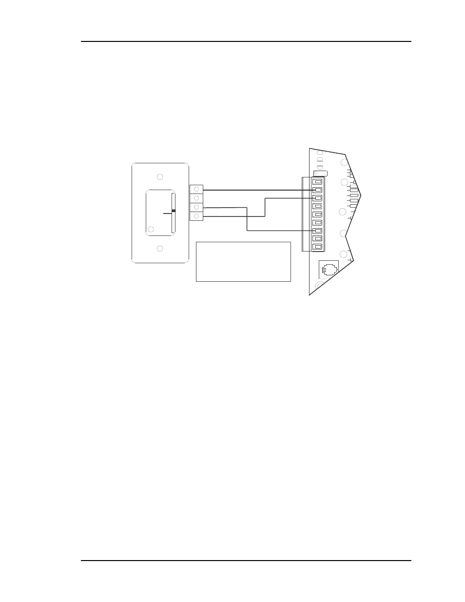
Figure 2-9:
Room Sensor Wiring
Connect the terminal labeled GND on the room sensor to the terminal labeled GND on
the CV Controller terminal block TB3. Connect the terminal labeled TMP on the room
sensor to the terminal labeled AIN1 on the CV Controller terminal block. If the room
sensor has a setpoint adjust slider, connect the sensor terminal labeled AUX to the CV
Controller AIN2 terminal block.