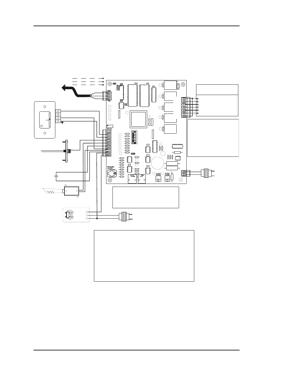
Cv controller wiring, Figure 4-9: typical cv controller wiring diagram – Auto-Zone Control Systems Auto-Zone CV & CV-EX Systems Installation & Operation (Version 01C) User Manual
Page 92
Section 4
Auto-Zone CV & CV-EX
4-14
Start-Up and Troubleshooting
CV Controller Wiring
Notes:
Line Voltage
Line Voltage
See Note 1 & 2
See Note 1 & 2
Wx or Yx (Htg or Clg Stage x)
Wx or Yx (Htg or Clg Stage x)
Wx or Yx (Htg or Clg Stage x)
Wx or Yx (Htg or Clg Stage x)
G (Fan-On/Off)
R (24VAC)
Constant Volume
Unit Connections
CV Controller
R
SH
T
R
SH
T
R
SH
T
R
SH
T
All Comm Loop Wiring Is
Straight Thru
Required VA For Transformer
Each CV Controller = 20VA Min.
24VAC
24VAC
GND
GND
Mount In HVAC
Unit Supply
Air Duct
Auxiliary Alarm
Input
Switch Supplied
By Others
Discharge
Air Temp.
Sensor
GND
AUX
TMP
NORMAL
OVR
R
E
L
O
C
R
E
M
R
O
A
W
Room Sensor
Local Loop
RS-485
9600 Baud
Connect To
Next Controller
And/Or
MiniLink On
Local Loop
Connection To
AUX Terminal is Reqd
Only When Sensor
Is Specified With
Slide Adjust Option
1.) 24 VAC Must Be Connected
So That All Ground Wires
Remain Common.
2.) All Wiring To Be In
Accordance With Local And
National Electrical Codes And
Specifications.
3.) All Communication Wiring To
Be 2 Conductor Twisted Pair
With Shield. Use Belden
#82760 Or Equivalent.
Economizer
Actuator
(Belimo Shown)
Consult Factory For
Other Manufacturers
Wiring Connections
Note:
Up To 4 Stages Of Heating Or
Cooling Or Any Combination Of Each
Is Allowed And Programmable Via
The System Manager or Computer
Front End Software. If The Unit Has
Heat, Heating Stages Must Be
Connected To The First Outputs in
Consecutive Order And Cooling
Stages To The Remaining Outputs In
Consecutive Order.
Outside Air
Temp. Sensor
(See Note 4)
4.) Only One Outside Air
Sensor Is Required Per
System. It May Be
Connected To Any CV
Controller On The System.
If The Wetbulb Module Is
Used, The OA Sensor Must
Be Connected To The
Wetbulb Module.
Y 3
+ 2
COM 1
AIN 1
+VDC
TB2
RELAY
OUTPUTS
AIN 2
AIN 3
AIN 4
AIN 5
GND
GND
AOUT
TB3
Caution:
When Wiring The CV Controller Be Sure To
Disconnect All Communication Loop Wiring
From The CV Controller Before Removing Power
From The CV Controller. Reconnect Power And
Then Reconnect Communication Loop Wiring.
T
SHLD
R
COM1-3
R1
R2
R3
R4
R5
TB1
24VAC
GND
COM4-5
EXPANSION
T'STAT
NETWORK
16
TOKEN
32
8
4
1
2
Figure 4-9: Typical CV Controller Wiring Diagram