Mechanical structure – BECKHOFF BC2000 User Manual
Page 11
Basic Principles
BC2000
10
The bus terminal controller can be made to enter the normal operating
state by switching it on again once the fault has been rectified.
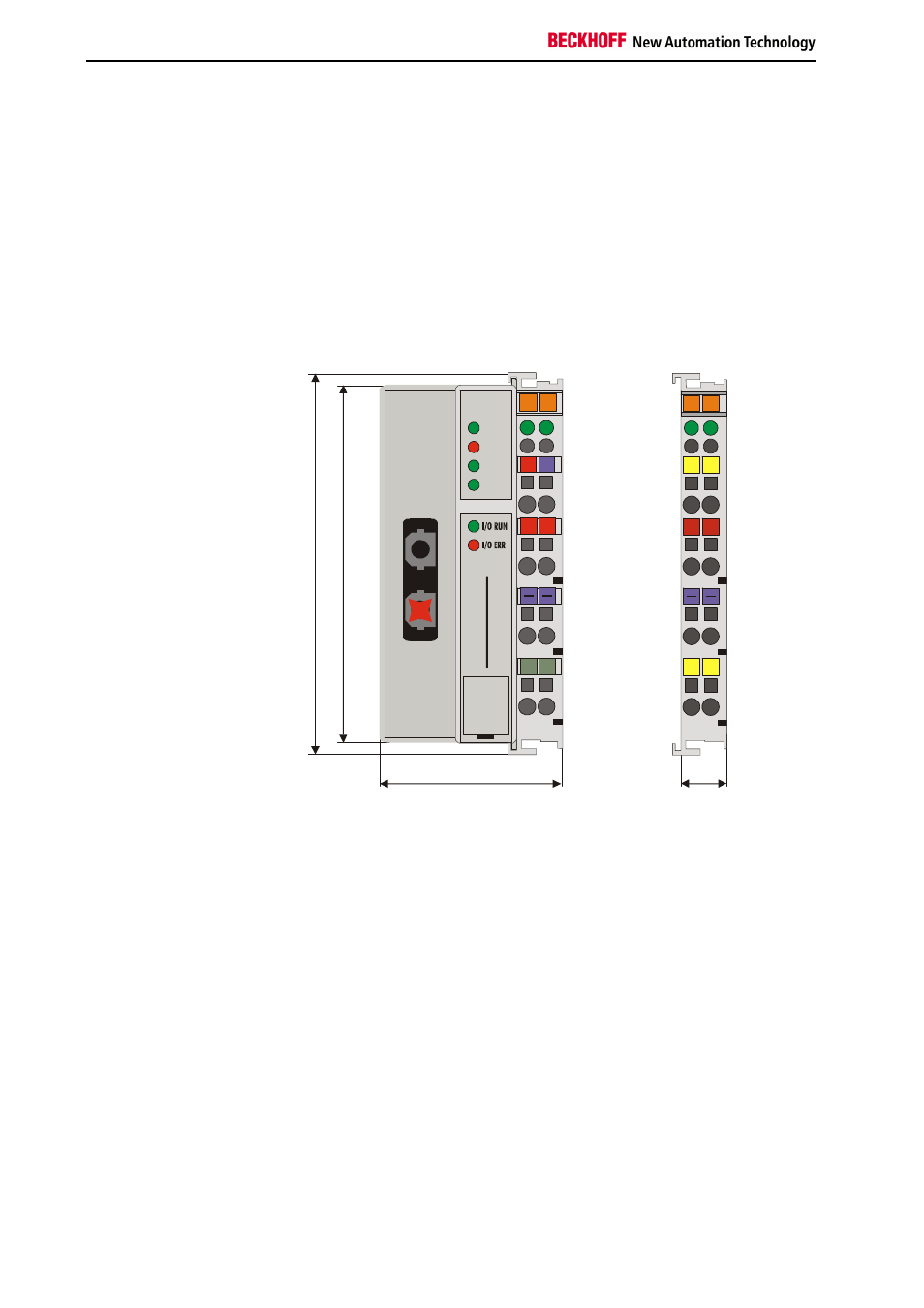
Mechanical structure
The system of the Beckhoff bus terminals is characterised by low physical
volume and high modularity. When planning a project it must be assumed
that at least one bus terminal controller and a number of bus terminals will
be used. The mechanical dimensions of the bus terminal controllers are
independent of the fieldbus system. If optical fibre cable with Z1000 plugs
is used, the clearances of the bus terminal controller are not exceeded.
Bus terminal controller
dimensions
10
0
94
49
12
02
01
+ +
PE PE
B
E
C
K
H
O
F
F
24V
0V
00
X0
CYC
ERR
WD
II/O-Lightbus
BC
20
00
E0
.0
+ +
00
.1
PE PE
PLC
The total width of the unit is composed of the width of the bus terminal
controller with the KL9010 bus end terminal plus the width of the bus
terminals being used. Depending on function, the bus terminals are 12 or
24 mm wide. The front wiring increases the total height of 68 mm by about
5 to 10 mm, depending on the wire thickness.
Assembly and connection
The bus terminal controller and all the bus terminals can be clipped by light
pressure onto a 35 mm C-mounting rail. A locking mechanism prevents the
individual housings from being pulled off again. For removal from the
mounting rail the orange coloured tension strap releases the latching
mechanism, allowing the housing to be pulled off the rail without any force.
Up to 64 bus terminals can be attached to the bus terminal controller on
the right hand side. When plugging the components together, be sure to
assemble the housings with groove and tongue against each other. A
properly working connection can not be made by pushing the housings
together on the mounting rail. When correctly assembled, no significant
gap can be seen between the attached housings.
The right hand part of the bus terminal controller can be compared to a bus
terminal. Eight connections on the top permit connection with solid or fine
wires. The connection is implemented with the aid of a spring device. The
spring-loaded terminal is opened with a screwdriver or rod, by exerting
gentle pressure in the opening above the terminal. The wire can be