The interfaces, Electrical power supply, Power contacts feeding points – BECKHOFF BC2000 User Manual
Page 8
Basic Principles
7
BC2000
Bus terminal controllers for
various fieldbus systems
Various bus terminal controllers can be used to couple the electronic
terminal strip quickly and easily to different fieldbus systems. It is also
possible to convert to another fieldbus system at a later time. The bus
terminal controller performs all the monitoring and control tasks that are
necessary for operation of the connected bus terminals. The operation and
configuration of the bus terminals is carried out exclusively by the bus
terminal controller. Nevertheless, the parameters that have been set are
stored in each bus terminal, and are retained in the event of voltage drop-
out. Fieldbus, terminal bus and I/O level are galvanically isolated.
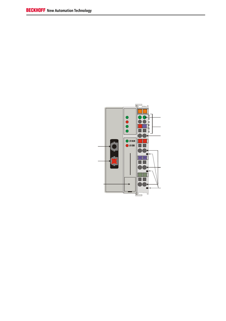
The interfaces
A bus terminal controller has six different methods of connection. These
interfaces are designed as plug connectors and as spring-loaded terminals.
The Beckhoff BC2000
Lightbus coupler
02
01
+ +
PE PE
B
E
C
K
H
O
F
F
24V
0V
00
X0
CYC
ERR
WD
II/O-Lightbus
BC
20
00
Power LEDs
Bus coupler / power contacts
Terminal bus (K bus)
II/O-Lightbus
IN
OUT
Configuration
and programming
interface
Bus coupler power supply
24 V DC / GND
Power contacts
feeding points
Power contacts
WD
PLC
Electrical power supply
24 V DC to the topmost
terminals “24 V” and “0 V”
The bus terminal controllers require a 24 V DC supply for their operation.
The connection is made by means of the upper spring-loaded terminals
labelled “24 V” and “0 V”. The supply voltage feeds the bus terminal
controller electronics and, over the terminal bus, the bus terminals. The
power supply for the bus terminal controller electronics and that of the
terminal bus are electrically separated from the potential of the field level.
Power contacts feeding points
Bottom 3 terminal pairs for
feed
Maximum 24 V
Maximum 10 A
The bottom six connections with spring-loaded terminals can be used to
feed the supply for the peripherals. The spring-loaded terminals are joined
in pairs to a power contact. The feed for the power contacts has no
connection to the voltage supply for the bus terminal controller. The design
of the feed permits voltages of up to 24 V. The assignment in pairs and the
electrical connection between feed terminal contacts allows the connection
wires to be looped through to various terminal points. The current drawn
from the power contacts must not exceed 10 A for long periods. The
current rating between two spring-loaded terminals is identical to that of the
connecting wires.