BECKHOFF AL2000 Linear servomotor User Manual
Page 23
Mechanical installation
surface, can be used for this purpose. Locating pins can be inserted into the round holes. Lateral positioning
of the coil unit with respect to the magnetic plates is not particularly critical. A tolerance of up to ±0.5 mm is
acceptable.
Please note the following comments and information.
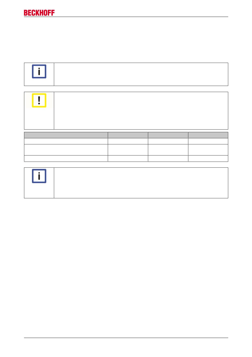
Notice
Screws
Fasten the screws in a crisscross pattern, so that the resulting forces are distributed evenly.
Attention
Damage due to screws that are too long
Using screws that are too long for the coil unit can cause damage that is not immediately
visible, and give rise to dangerous situations.
Check:
• the screw length
• the screw height after the installation.
Screws for the coil unit
AL20xx
AL24xx
AL28xx
Screw (steel)
M5
M4
M5
Depth in the coil unit
Min: 4 mm
Max: 5mm
Min: 4 mm
Max: 5 mm
Min: 4,5 mm
Max: 6.5 mm
Tightening torque
3.0 – 5.0 Nm
2.0 – 3.0 Nm
3.0 – 5.0 Nm
Notice
Water cooling
Note that the connections for the water cooling can extend up to 1 mm beyond the dimen
sions of the coil part. Ensure that enough clearance is maintained, or else use a spacer
plate at least 1 mm thick. See also the section entitled Installation of the water cooling [
44] (additional installation instructions / water cooling).
Linear servomotor AL2xxx
23
Version 4.0