Cloud Electronics CDPM Range User Manual
Page 10
CDPM Digital Paging Microphone
Setup And Installation Guide
CLOUD ELECTRONICS LIMITED
✁
✂
✄
☎
✆
✆
✝
✞
✟
✠
✆
✡
✟
☛
✝
✄
☞
✌
✍
✟
☎
✎
✏
✠
✑
✝
✒
✓
✔
✠
✆
✡
✕
✖
✗
RJ45 connections between the CDPM and a mixer are pin-to-pin.
The conventional core connections between Cat-5 and RJ45
plugs is shown in Table 5.2.
A network using this connection type should have a total cable
length less than 1km. Where a mixer has facility for both RJ45
and access contact connection, the RJ45 connection should be
used.
NOTE: Mixers will only receive audio from CDPMs that have connected ‘OUT’ towards the mixer
network location. It is possible to connect a mixer at any point within the network, however an
intermediate mixer will not be able to receive audio from microphones connected ‘IN’.
✁
✘
✄
☎
✆
✆
✝
✞
✟
✠
✆
✡
✟
☛
✝
✄
☞
✌
✍
✟
☎
✎
✏
✠
✑
✝
✒
✙
✠
✟
☛
✔
☛
☎
✒
✟
✚
✟
☎
✚
✡
✒
☎
✓
✆
✛
✞
☎
✆
✟
✎
✞
✟
✔
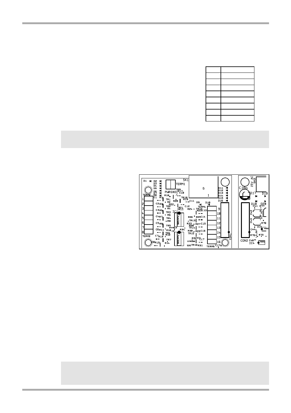
An optional analogue module is
available to fit inside the CDPM
microphones which can be used to
connect a CDPM microphone
network to the short-to-ground
paging terminals on a mixer. If
fitted, this module is located
directly behind the ‘AUDIO OUT’
XLR socket on the rear of the
CDPM. Connection to the mixer is
via board mounted screw terminal
blocks where the number of each
terminal corresponds to the
network zone of that number.
Refer to section 6 for installation
instructions.
There are two cables required for connection to the analogue interface:
Audio Cable: The audio cable should be a standard two-core, screened, microphone audio
cable. This cable is connected to the XLR socket marked 'AUDIO OUT' on the rear panel.
Connections to this XLR are pin-2 as in phase (hot), pin-3 as inverse phase (cold) and the
connector shield as a ground termination
Control Cable: The control cable should contain a core for each zone to be connected to it and
a core for the 'GND' connection. This cable should also be screened, but this should be separate
to the 'GND' connection. If the CDPM is to be powered from the Cloud host mixer then an
additional core is required on the control cable.
The control cable should be inserted through the rear panel via a cable gland fitted to the hole
marked 'ANALOGUE PORT'. A suitable cable gland is provided with the analogue interface. For
installation and connection details, refer to section 6 of this manual.
NOTE: Connections to this terminal should have a total cable length of less than 100m.
NOTE: Mixers will only receive audio from CDPMs that have connected ‘OUT’ towards the mixer
network location. It is possible to connect a mixer at any point within the network, however an
intermediate mixer will not be able to receive audio from microphones connected ‘IN’.
4
V1 210605
Fig 5.3: Screw terminal locations
Table 5.2: RJ45 Connections
RJ45 CAT-5
Pin 8 Brown/White
Pin 7 White/Brown
Pin 6 Green/White
Pin 5 White/Blue
Pin 4 Blue/White
Pin 3 White/Green
Pin 2 Orange/White
Pin 1 White/Orange