Cloud Electronics CDPM Range User Manual
Page 19
CDPM Digital Paging Microphone
Setup And Installation Guide
CLOUD ELECTRONICS LIMITED
The first rack of equipment is to be located close to the kitchen, since this area is a service area
and not in the public view. The second rack is placed in a storage area of the gym. To simplify
the cabling between the different areas, it is determined that both the gym and kitchen CDPM-4s
will have an analogue interface module installed. This allows each of these to be powered from
a mixer, and means that there is no need for an analogue set of cables to run between the
kitchen and the gym.
One of the installation requirements, is that certain groupings are set and recognised, but cannot
be reconfigured by the end users of the microphones. As such the groups will be set on
initialisation for the CDPM-12 microphones, and all microphones will operate with the group lock
on to prevent users tampering with the group settings.
To initialise the microphones, the CDPM-PSU can be used to connect power to each of the units.
To initialise a unit it will need to power up with the NVM reset jumper ‘ON’ (J7). Once the unit
has powered up the zones that are not being used should be disabled. This is done by holding
down the ‘CLEAR’ button and then selecting those zones which are to be disabled. Once the
required zones have been selected, the ‘CLEAR’ button on the microphone can be released. For
the CDPM-12 microphones, buttons 11 and 12 are to be disabled; for the Gym microphone,
button 4 is to be disabled.
In this same initialisation stage, the CDPM-12 groups can be set. These are set by selecting the
required zones on the display and then holding the appropriate group button until the selection
begins to flash. The groups are to be set as follows:
Group A - Zones 1, 2 and 4
Group B - Zones 6 - 8
Group C - Zones 3 and 5
Group D - Not set
The security microphone is to use chime 1 from the available selection and the security
microphone is to use chime 4. The other two paging points are not to use any chime.
Once the initialisation of each of the microphones is complete, the power is disconnected and
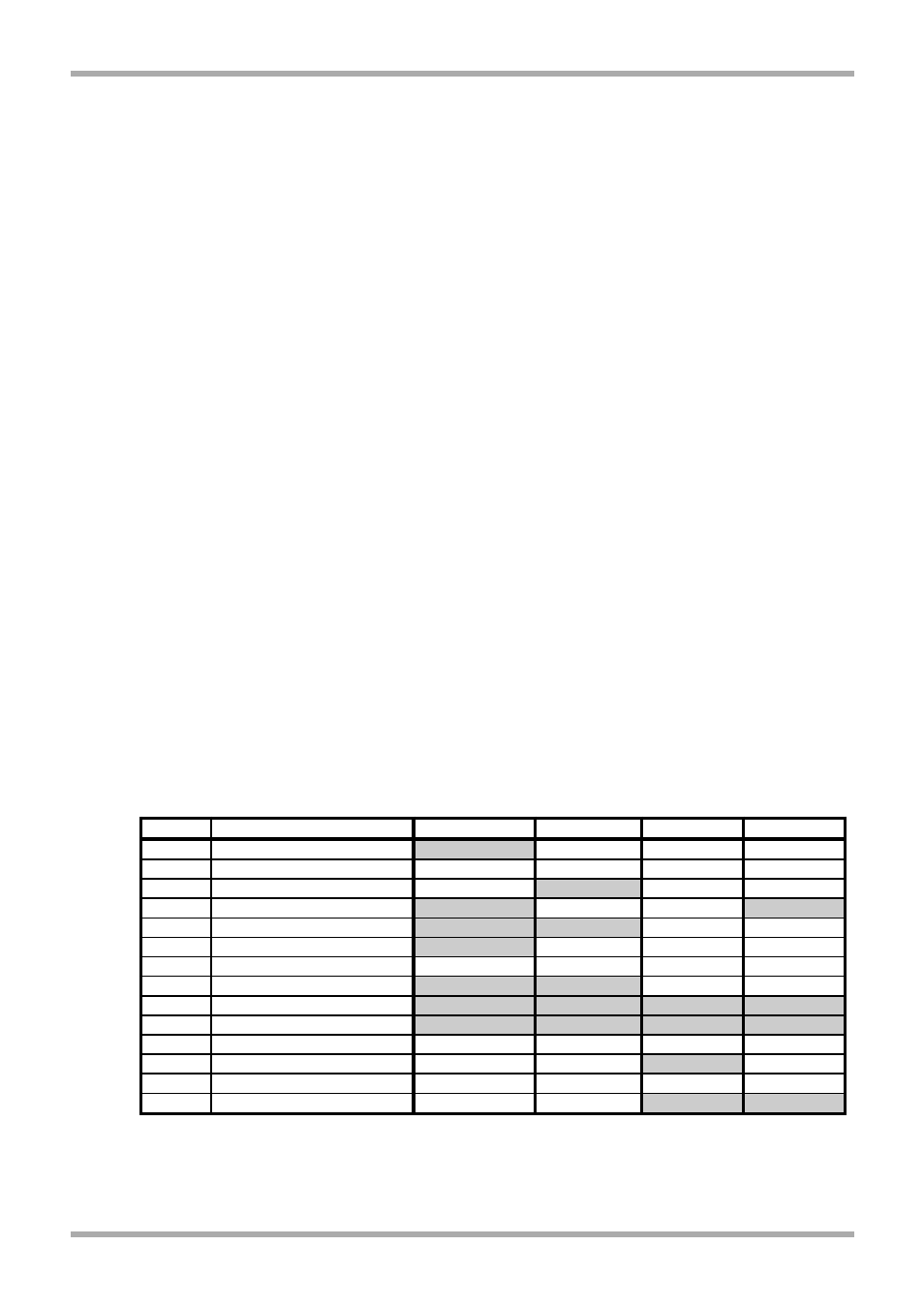
the units are configured for operation before they are installed. The operating jumper
configuration for each microphone is shown in table 9.3 below:
Table 9.3: Operating jumper configurations for Paging Points
Once this configuration has taken place, the chime level on the Reception and Security
microphones will need to be adjusted to an appropriate level using preset PR1 inside these
microphones.
Jumper
Description
PP1:Reception PP2:Security
PP3:Gym
PP4:Kitchen
J1
+1 to Chime Select
ON
OFF
OFF
OFF
J2
+2 to Chime Select
OFF
OFF
OFF
OFF
J3
+4 to Chime Select
OFF
ON
OFF
OFF
J4
Terminate Buss
ON
OFF
OFF
ON
J5
Chime On/Off
ON
ON
OFF
OFF
J6
Internal Chime On/Off
ON
OFF
OFF
OFF
J7
NVM Reset
OFF
OFF
OFF
OFF
J8
Priority
ON
ON
OFF
OFF
J9
Group Lock
ON
ON
ON
ON
J10
Auto Zone Reset
ON
ON
ON
ON
J11
+8 to Bank Offset
OFF
OFF
OFF
OFF
J12
+4 to Bank Offset
OFF
OFF
ON
OFF
J13
+2 to Bank Offset
OFF
OFF
OFF
OFF
J14
+1 to Bank Offset
OFF
OFF
ON
ON
13
V1 210605