Cloud Electronics CDPM Range User Manual
Page 9
CDPM Digital Paging Microphone
Setup And Installation Guide
CLOUD ELECTRONICS LIMITED
✁
✂
✄
☎
✆
✝
✞
✟
✠
✡
☛
✞
☎
☞
✌
✍
✎
☎
✏
✑
✒
☎
✓
✔
☞
✟
✕
✝
✞
For CDPM units on the network which are to be connected to a mixer, it is possible to power the
CDPM from the mixer as long as the capacity of the mixer is sufficient and the mixer has a power
supply connection for paging microphones. As a general rule, a mixer cannot supply to a CDPM
that has more zones than the mixer. If the mixer is supplying power to other optional modules
in addition to the CDPM then the mixer may be stretched beyond its capacity. In such cases, an
external adapter must be used for the CDPM. For specific details of Cloud mixer current
capacities and requirements of each optional module, see tables 4.2.1 and 4.2.2 below.
There are two ways in which a CDPM can connect to power on a Cloud host mixer. The RJ45
‘OUT’ connection on the CDPM carries power, so the last microphone in the network will obtain
power from this connection if it is connected to a mixer, and no external power supply is
connected to the microphone. The optional analogue interface also has a ‘PWR’ screw terminal
which should be connected to the ‘+V’ connection at the Cloud host mixer. This connection
requires an additional core in the access cable.
Each CDPM is fitted with two RJ45 sockets labelled ‘CAN PORTS’. These sockets are for the custom
interface the CDPM microphones use to communicate. Audio is directional on this interface, and so is
transmitted from the ‘OUT’ connection to the ‘IN’ connection on the next microphone or mixer in the
chain. The CDPM microphone can also be connected to a mixer using the industry-standard, short-to-
ground paging system when using the optional analogue interface.
✖
✁
✗
✍
☎
✠
✠
✝
✘
✔
✟
✠
✡
✙
✝
✔
✆
✝
✝
✠
✍
✚
✄
✛
☞
✟
✘
✞
☎
✜
✒
☎
✠
✝
✓
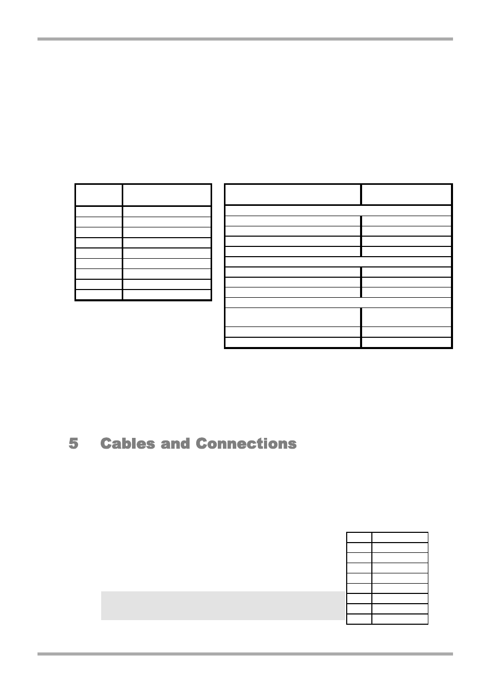
Using the RJ45 connections on the rear of the CDPM, the 'OUT'
port of a CDPM should be connected to the 'IN' port of the next in
the chain. Connections are pin-to-pin between the two ends of the
cable. The standard Cat-5 to RJ45 wiring convention is shown in
table 5.1.
NOTE: The RJ45 network must be terminated at both ends. See
section 7.9 of this manual to find details of how to terminate the
Clouod Paging Interface buss.
3
V1 210605
Unit
Required Current
(mA)
CDPM Paging Microphones
CDPM-4
72
CDPM-8
83
CDPM-12
95
CDPM-16
107
Active Remotes
LM-1
12
DM-1
18
AE-1
9
Equalisation Modules
BEQ: M8, M32, MA12, 402, 502A, 802,
MB4, MB24, 502B, 502BEX
12
BEQ: LT3202, LT4402, LT9402, LT9702
17
BEQ: M16
24
Unit
Available Current
(mA)
36/50
Use External PSU
46/50
80
CX163
Use External PSU
CX263
Use External PSU
CX462
80
Matrix 4
Use External PSU
MPA-626
Use External PSU
Z4ii
120
Z8ii
190
Table 4.2.1: Power Supply Capacities
Table 4.2.2: Optional Module Power Supply Requirements
Table 5.1: RJ45 Connections
RJ45 CAT-5
Pin 8 Brown/White
Pin 7 White/Brown
Pin 6 Green/White
Pin 5 White/Blue
Pin 4 Blue/White
Pin 3 White/Green
Pin 2 Orange/White
Pin 1 White/Orange