Cloud Electronics CDPM Range User Manual
Page 17
CDPM Digital Paging Microphone
Setup And Installation Guide
CLOUD ELECTRONICS LIMITED
✁
✂
✄
☎
✆
✆
✝
✞
✟
✠
✆
✡
☛
✄
☞
✌
✍
✎
✏
✟
☎
☛
✏
✑
✒
✓
✔
In this use case, an installation of four zones is considered, where the CDPM-4 is to be used in
conjunction with a 46/50 mixer-amplifier. There is a requirement for a single paging point, so no
further microphones will be required.
The 46/50 only supports paging microphone connection via a set of analogue access contacts,
so the CDPM-4 will require the analogue interface module. Section 7.10 is used to determine
which jumpers will need changing to configure the Mic 1 input on the 46/50 for use as a paging
microphone input, since this input is a dual purpose input. Since there is only a single
microphone, this unit can be powered from the mixer connections, a CDPM-PSU will not be
required.
Since the installation is small, there is no requirement for the group buttons to be set so the
microphone jumpers can simply be set for operation without initialising any groups. J9 is set to
ON to prevent any groups being set and J10 is set to ON in order to clear a zone selection once
the call has been made. All the other jumpers inside the unit can be left at the factory default
settings.
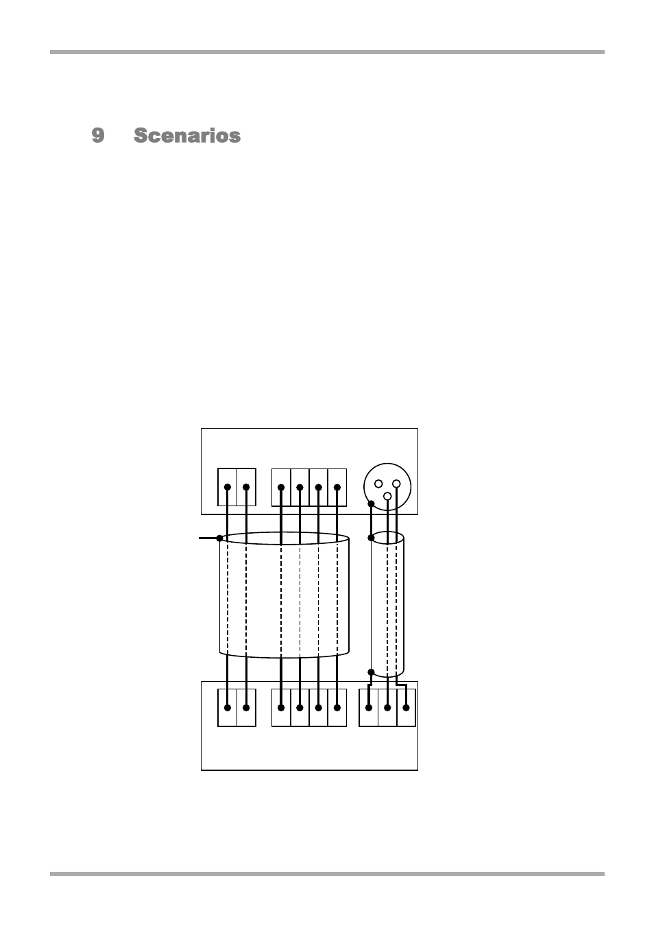
Connections between the two units are shown on the diagram below.
Figure 9.1.1: Connections between a single CDPM-4 and a 46/50
PWR GND
+V
3
1
4
2
2
1
3
0V
CDPM-4 Analogue Module
46/50 Mic 1 connections
1
2
3
4
Access Contacts
Mic 1 input
TO GLAND
CHASSIS
CONNECTION
1
2
3
XLR
11
V1 210605