Ia500, Administrator guide 5 installation – Code Blue IA500-S SINGLE BUTTON ANALOG SURFACE MOUNT User Manual
Page 6
Code Blue
•
259 Hedcor Street
•
Holland, MI 49423 USA
•
800.205.7186
•
www.codeblue.com
GU-144-E
page 6 of 17
IA500
Administrator Guide
5 Installation
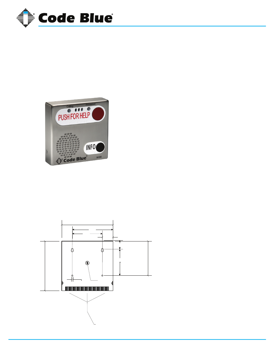
The IA500 Series comes in surface and flush mount options. The surface mount allows the
mounting bracket to be installed during rough in and the faceplate with electronics during
completion. The faceplate on the flush mount is five inches square and provides an overlap to the
mounting box to eliminate additional trim work.
7.
00
in
.
7 1/4"
3/16"
1 5/16
4 1/4
Ø 1/2"
Three ½-inch conduit
openings are available
through the
bottom of this panel
1 1/2"
5 3/4
3.72
4
7/
8"
REQUIRED MATERIALS
•
Cat 3 shield twisted phone wire
•
4 - #8 screw (fasteners)
• To install the IA500, first remove the two retaining screws
(Allen wrench provided), from each side of the case.
• Remove the rear mounting plate by sliding it downward.
• Using the mounting plate as your guide on the wall, mark
the mounting hole and conduit hole locations on the wall.
• Remove the rear mounting plate and create the required
holes, along with any conduit you choose to use. Attach
rear mounting plate to wall.
• Pull CAT 3 shield twisted pair wire through the conduit
opening in the rear mounting plate, and leave nine inches
of CAT 3 wire beyond the wall.
• Strip the tip and ring wires and attach them to the IA500
(PCB) screw terminals marked tip and ring.
• Slide the IA500 down, starting from the top of the rear
mounting plate until the bottom of the IA500 comes flush
with the rear mounting plate lip.
• Replace the two retaining screws.