Description, 2 description – Comtech EF Data DST User Manual
Page 21
Digital Satellite Terminal System
Revision 2
Introduction
MN/DST.IOM
1–3
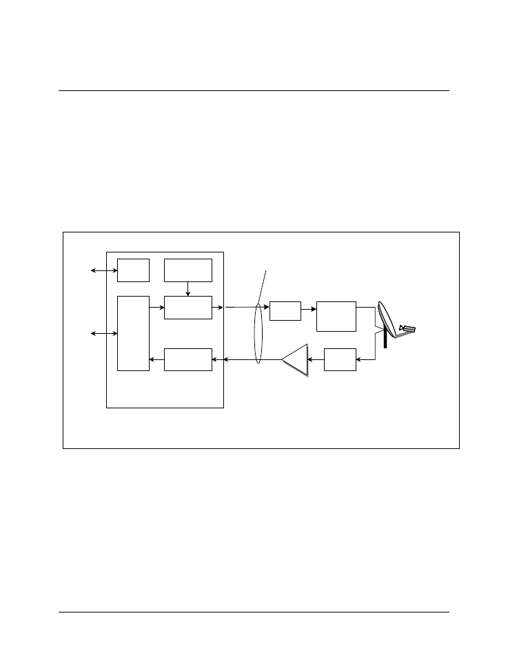
1.2 Description
The DST is an integrated, single thread, Single Channel Per Carrier (SCPC), Very Small
Aperture Terminal (VSAT) system designed to meet the needs of a single and/or multiple
site installations.
A block diagram of the DST system is shown in Figure 1-2.
Note: The antenna and the Ortho Mode Transducer (OMT) are not part of the DST
system. The Transmit Reject Filter (TRF), Receive Reject Filter (RRF), and L-Band
Inter-Facility Link (IFL) cables are optional equipment as are mounts.
Figure 1-2. DST System Block Diagram
Tx IF
Rx IF
BUC
LNB
LNB
Modulator
Modulator
ODU
Power Supply
ODU
Power Supply
M&C
M&C
IFL Cables
(Optional)
Demodulator
Demodulator
Data
Interface
Data
Interface
Tx Reject
Filter
(Optional)
Tx Reject
Filter
(Optional)
Feed Horn, OMT And
Antenna Not Provided
Mounting Kits Optional
Rx Reject
Filter
(Optional)
L-Band Modem