Trf installation – Comtech EF Data DST User Manual
Page 51
Digital Satellite Terminal System
Revision 1
Low Noise Block Converter
MN/DST.IOM
4–9
Note: Flat washers maybe omitted if there is interference with assembly.
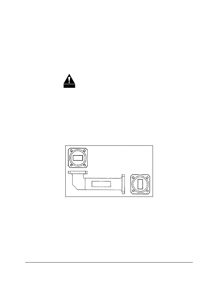
4.4.6 TRF
Installation
To install the TX Reject Filter to the antenna OMT:
1. If installed; remove protection covers from the OMT and TRF.
CAUTION
After removing the protective covers, ensure that no foreign
material or moisture enters the antenna waveguide or TRF.
2. Install the appropriate gasket (from KT/8924-1 or KT/2721-1)on the antenna
OMT or TRF, as follows:
a. If only one of the mating flanges is grooved, the thin gasket should be
installed.
b. If both of the mating flanges are grooved, the thick gasket should be
installed.
3. Position the TRF (with ogasket) in place on the antenna OMT and install with
provided No. 6 SAE hardware, from Mounting Kit Part No. KT/8924-1 or
KT/2721-1
Figure 4-3. TRF Installation (Ku-Band Shown)