Carrier spacing and frequency uncertainty – Comtech EF Data DST User Manual
Page 60
Digital Satellite Terminal System
Revision 1
Operation
MN/DST.IOM
A–2
A.1.2
Carrier Spacing And Frequency Uncertainty
When there is no carrier uncertainty, the carrier spacing is usually 1.3 * SR, where SR is
the symbol rate of the modem. More generally, the carrier uncertainty is:
fv
≤ SR * 2 * k, or
SR
≥ fv /(2 * k)
where,
fv = Total One Sided Frequency Variation or Uncertainty
SR = Symbol Rate
k = Carrier Spacing Factor, usually 1.3
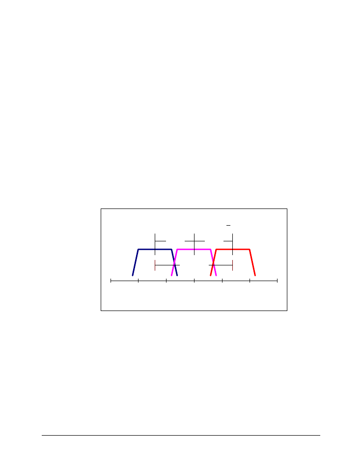
The factor of 2 appears because the uncertainty is
±fv. The maximum carrier uncertainty
is illustrated in Figure A-1 where the ideal position of the carrier is shown in the center,
and its location due to uncertainty is displaced to extreme positions of +fv and -fv relative
to the ideal. Because the goal is to establish the minimum symbol rate for a given
frequency uncertainty fv is expressed in terms of symbol rate (SR) and Carrier Spacing
Factor (k).
Figure A-1. Maximum Carrier Uncertainty, fv, expressed
in terms of Symbol Rate, SR
The most efficient spectral utilization is obtained when the symbol rate is high enough
that a k * SR spacing factor is usable. This requires that fv is smaller than the carrier
spacing to prevent locking to the wrong carrier. Alternatively, if the carrier spacing is too
small compared to fv it is necessary to increase the spacing. For a typical link carrier
spacing is 1.3 * SR, when k = 1.3, and this is still acceptable as long as SR
≥ fv /(2 * 1.3).
When the uncertainty, fv, is higher, then k
≥ 1.3 is needed resulting in a wider spacing
between the carriers.
Maximum Carrier Uncertainty, fv < 2 * k * SR
-15
-10
-5
0
5
10
15
Relative Frequency
k x SR
k x SR
fv_max
< 2 * k * SR
k * SR
k * SR