Radio interference, Radio receiver (all sport 5000) – Daktronics Outdoor LED Scoreboards Service Manual User Manual
Page 20
14
Scoreboard Troubleshooting
o
If there is no clock, the settings should appear in the Home and Guest score
digits, but this may vary by scoreboard model.
o
Scoreboards capable of displaying speed of pitch may also have separate
radio settings for the second All Sport console controlling those digits.
When using the RC-100 controller,
the scoreboard will display “CXX”,
where the XX is a channel from 01-
15 (Figure 14). The default is
channel 01.
Note: If these settings do not appear,
the radio receiver may need to be repaired/replaced.
To make sure the console radio settings (Figure 15)
match the receiver in the scoreboard, refer to the
Radio Interference
If it has been determined that a nearby scoreboard’s radio signal is interfering, the settings of
the wireless base station or radio receiver inside the scoreboard(s) must be changed.
1. To locate the radio receiver or base station, simply look for the black antenna sticking
out the front of the scoreboard. Component location drawings also show the exact
position where the radio receiver will be mounted.
2. Open the access panel to which the receiver is attached as described in Section 2.2.
The channel selection process varies depending on whether the scoreboard is equipped with
or a radio receiver (All Sport 5000) or a base station (RC-100).
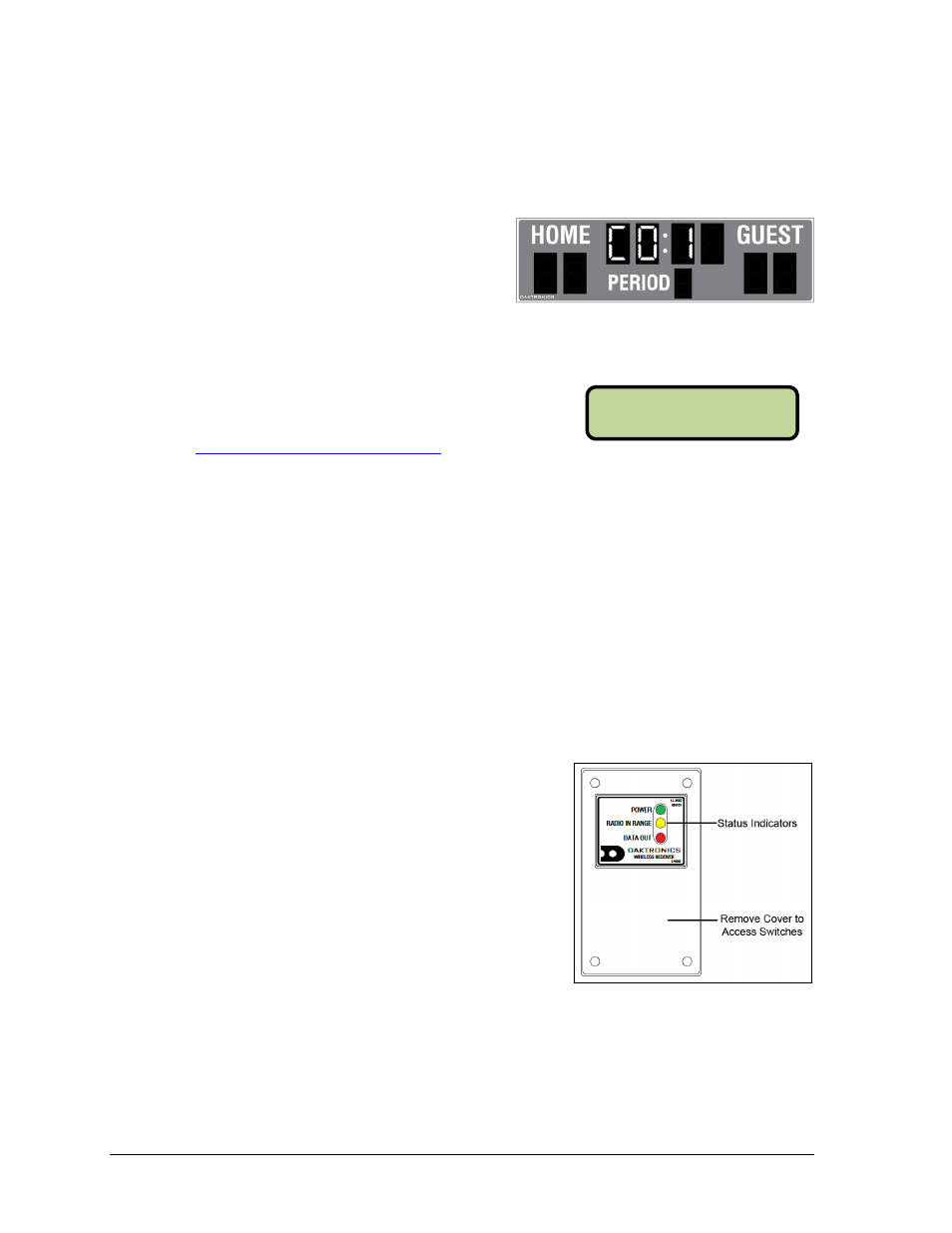
Radio Receiver (All Sport 5000)
1. The radio receiver has a plastic cover with a
window to view status indicators (Figure 16).
Note: While it is necessary for the scoreboard to
be powered on to check the indicators, always
disconnect scoreboard power before servicing.
2. Remove the four screws in each corner using a
#2 Philips screwdriver and lift off the cover.
3. The process of changing the radio settings
depends on the generation of the radio. Refer to
the instructions below and Figure 17.
Gen V (blue label): Use a small flathead screwdriver to set the CHAN switch to
a new channel (1-8). Move the jumper wire on the J4 or J5 BCAST jacks to a new
broadcast group (1-4) as needed.
Gen VI (gray label): Use a small flathead screwdriver to set the CHAN and
BCAST switches to a new channel and broadcast group (1-8) as needed. Be sure
to always leave FUNC set to “1”.
Figure 14: RC-100 Radio Settings (Clock)
Figure 15: Radio Settings (Console)
Figure 16: Radio Receiver w/ Cover
RADI O SETTI NGS
BCAST 1 CHAN 01