Optional temperature sensor mounting, Optional temperature sensor mounting -3, Figure 9: temperature sensor eave/wall mount -3 – Daktronics AF-3065-34-RGB User Manual
Page 15
It is the responsibility of the installer to ensure the installation will adequately meet local codes
and standards. The mounting hardware and method is also the responsibility of the installer.
Before beginning the installation process, verify the following items.
·
The mounting structure will provide a straight and square mounting frame for the display. Height
variation in any four-foot horizontal section may not exceed ¼-inch.
·
The mounting structure will not give way at any unsupported points after the display is mounted.
The back of the display is equipped with 2 x 2 x ¼
² steel clip angles at the locations shown in
Drawings A-128799 and A-128801. These angles may be used for mounting purposes. Remember to
have all mounted displays inspected by a qualified structural engineer. It is the customer’s
responsibility to determine the proper wall mounting method and location.
Refer to Drawing A-128799 for a suggested wall mount method. The number of attachment points
needed and the wall structure must be reviewed by a qualified structural engineer and meet all national
and local codes. Daktronics recommends using all clip angles as attachment points.
1. Carefully uncrate the display. Look each side of the display over for damage during shipping.
2. Following the guidelines described in Section 2.4, lift the display into position on the support
structure.
3. Weld or use ½
² Grade-5 bolts and hardware to secure the clip angles to the support structure as
shown in Detail A in Drawing A-128799.
4. Refer to Section 3 for information on routing power and signal.
5. After installation is complete, carefully inspect the display for any holes that may allow water to
seep into the display. Seal any openings with silicone. If the eyebolts on the top of the display
have been removed, plug the holes with bolts and the rubber sealing washer that was removed
with the eyebolt.
Mechanical Installation
2-3
2.6
Optional Temperature Sensor Mounting
The optional temperature sensor is mounted
separately and requires a location away from
the influence of chimneys, air conditioners,
vents, tar roofs, concrete and parking lots
which can cause abnormal temperature
fluctuations. Usually a separation of at least 20
to 30 feet horizontally and eight feet vertically
is required to achieve this. Locations where air
movement is restricted are also unsatisfactory.
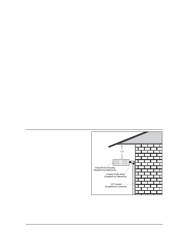
A first-choice temperature sensor location is a
north eave or northern exposure away from
direct sun light and above grass. This location
gives extra stability and accuracy to the sensor
because of the added shading usually obtained
on a northern exposure. There should be at
least one foot between the bottom of the eave
and the top of the temperature sensor housing
for accurate readings, as seen in Figure 9.
Due to the nature of the signal cable used to send the temperature information, the maximum distance
between the temperature sensor and the display is 1,000 feet (304.8 meters).
Figure 9: Temperature Sensor Eave/Wall Mount