Power summary, Service & diagnostics, Power summary -2 – Daktronics AF-3065-34-RGB User Manual
Page 28: Service & diagnostics -2
4.3 Power
Summary
Reference Drawing:
Schematic ...................................................................................................... Appendix B
The power routing for the display can be summarized as follows.
1. Incoming power terminates at the power termination enclosure. Before leaving the enclosure,
power is sent through a circuit breaker and an RFI electrical filter.
2. Power for the controller board passes through a transformer located on the controller/power panel.
3. Depending on display size, either +6.5VDC or +9VDC power supplies are used to power the
modules. Power supplies are preset. Contact Daktronics Customer Service for the proper settings.
4. In Galaxy displays, the 9VDC power supply powers the green and blue LEDs through the 4-pin
connector. The 6.5VDC power supply powers the red LEDs and driver’s logic circuit through 2-
pin connectors.
4.4
Service & Diagnostics
Reference Drawings:
Signal
Input, Venus 1500 .................................................................... Drawing A-129110
Assy, Power Supply A-1633 @2, A-1591 ............................................ Drawing A-148636
Entrance Box 8/16............................................................................... Drawing A-149160
Assy, Power Box 2 Position................................................................. Drawing A-155736
Exploded
Front, Module ...................................................................... Drawing B-126111
Exploded Rear, Module ....................................................................... Drawing B-126112
Component Layout Diagram........................................................................... Appendix B
Schematic ...................................................................................................... Appendix B
The following sub-sections address servicing of the following display components:
·
transformer, RFI filter
·
controller
·
modules, drivers and power supplies
The sub-sections also address any diagnostic LEDs, fuses and signal/power connectors found on the
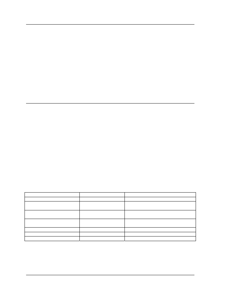
unit. On the Schematics and Component Layout Diagrams, the components are denoted as follows.
Component… Denoted
As…
Location…
Filter & Transformer
0A-1241-4002
Inside the power termination box
Controller
0A-1146-0067
Inside the controller/power panel (behind
the bottom left module)
Modules Squares
(0A-1208-2551)
A101 through A418
Over entire face of the display (includes
driver)
Power Supplies
0A-1241-4001
0A-1213-4034
Behind modules (refer to your display’s
schematic)
Light Detector
0A-1241-4001
Behind the bottom left module
Modem
0P-1146-0003
Refer to the display’s schematic
Fiber Board
0P-1127-0024
Refer to the display’s schematic
Maintenance &
4-2
Troubleshooting