Removing the louver assembly, Power supplies, Power supplies -5 – Daktronics AF-3065-34-RGB User Manual
Page 31: Figure 22: removing a module -5
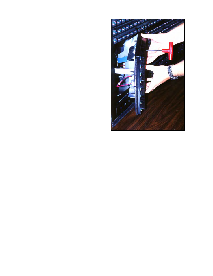
When installing a module, reverse the
previous steps and take note of the following
points:
Figure 22: Removing a Module
·
The weather-stripping on the back edge
of the module must be intact and in good
condition if it is to prevent water from
seeping into the display.
·
The module latches must be fully
engaged to create a watertight seal around
the edge of the module. The module
should be firmly seated against the
display when the latches are fully
engaged.
Each module assembly is made up of a
module housing (containing LEDs and the
driver) and a louver assembly. Drawings B-
126111 and B-126112 illustrate the various
module components.
From time to time, it may become necessary
to remove one or more parts from the module
housing for repair or replacement. The
following sub-sections explain how to
disassemble a module.
Removing the Louver Assembly
Complete the following steps to remove the louver assembly from the face of the module.
1. From the backside of the module, remove the five twist-on fasteners holding the louver
assembly to the module.
2. Lift the louver assembly straight away from the module.
Damaged louvers may reduce the brightness and contrast of this display. If any of the louvers
on the display are broken or damaged, the entire louver assembly must be replaced. Refer to
the Replacement Parts List in Section 4.11. When replacing the louver assembly take care not
to strip the plastic twist-on fasteners.
Power Supplies
The LED power supplies are identified as assemblies 0A-1241-4001 in the component location
drawings.
Complete the following steps to remove a power supply from the display:
1. Remove the module directly in front of the failed power supply.
2. Disconnect all the wires connected to the power supply.
3. Remove the hardware holding the power supply in place to free the unit.
4. Follow these steps in reverse order to install a new power supply. Refer to the display’s
Schematic when reconnecting the wires.
Maintenance &
Troubleshooting
4-5