Rj connector cables, Installing an rj connector, Pin-outs – Daktronics AF-3065-34-RGB User Manual
Page 19: Rj connector cables -3, Installing an rj connector -3, Pin-outs -3, Figure 17: flipped cable with rj connectors -3, Figure 18: wire with outer jacket stripped -3
3.3
RJ Connector Cables
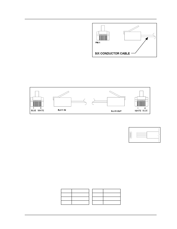
The conductor connector used in the network is an
industry standard, 6-pin RJ11. This connector can
be found on many telephones and LANs.
Figure 16: 6-Conductor RJ-11 Connector and Cable
The cable used in the network is a standard flat
six conductor telephone cable (standard flipped
cable). Refer to Figure 16. This cable has one end
that is the mirror image of the other end (i.e. the
cable is flipped). Refer to Figure 17 for a
standard flipped cable.
Notice in Figure 17 that the color code on one connector must be made the opposite on the other
connector. When installing a network, it is not easy to remember in which direction the previous end
was oriented. One simple way to avoid confusion is to standardize the color code, having one color for
the connector going into the output of a sign and the opposite color for a connector going into the
input of a sign. This will help ensure correct cabling since cables are always installed from the output
jack of one sign to the input jack of the next sign.
Figure 17: Flipped Cable with RJ Connectors
Installing an RJ Connector
Electrical Installation
3-3
Installing an RJ connector on the end of the conductor cable is a simple
task when the correct tools are used. The RJ crimping tool (Daktronics part
number TH-1033) performs two separate steps.
First, use the crimping tool to strip the outer insulation from the inner
wires. This does not result in bare wires since only the gray outer jacket is
removed. After correct stripping, the wire will appear as shown in Figure 18.
Figure 18: Wire with
Outer Jacket Stripped
The crimping tool is then used to crimp the RJ connector onto the cable. The RJ connector is
locked into a special socket in the tool. The stripped wire is inserted into the RJ connector.
Finally, the tool is squeezed like a pliers to crimp the connector onto the wire. This completes the
installation of an RJ connector onto the wire.
Pin-Outs
The RS422 jack’s pin out is as follows:
RJ11 Function
RJ11
Function
1 GROUND
4 D1IN-P
2 D1OUT-P
5 D1IN-N
3 D1OUT-N
6 GROUND