Light detector, Modem, Fiber board – Daktronics AF-3065-34-RGB User Manual
Page 32: Light detector -6, Modem -6, Fiber board -6, Figure 23: modem -6, Figure 24: fiber optic board -6
Light Detector
The light detector is internally mounted and wired at Daktronics. It is located in the bottom left
corner on the front of the display (identified as assembly 0A-1241-4001 (LT) in the Component
Layout Diagram). A 4-conductor cable connects the light detector to the controller board. The
cable is terminated at the terminal block on the light sensor and at TB7 on the controller board
(refer to your display’s schematic).
Light Detector
Pin No.
Cable Wires
Color
Controller Board
TB7 Pin No.
1 Green 3
2 White 4
3 Red 1
4 Black 2
N.C. Shield
2
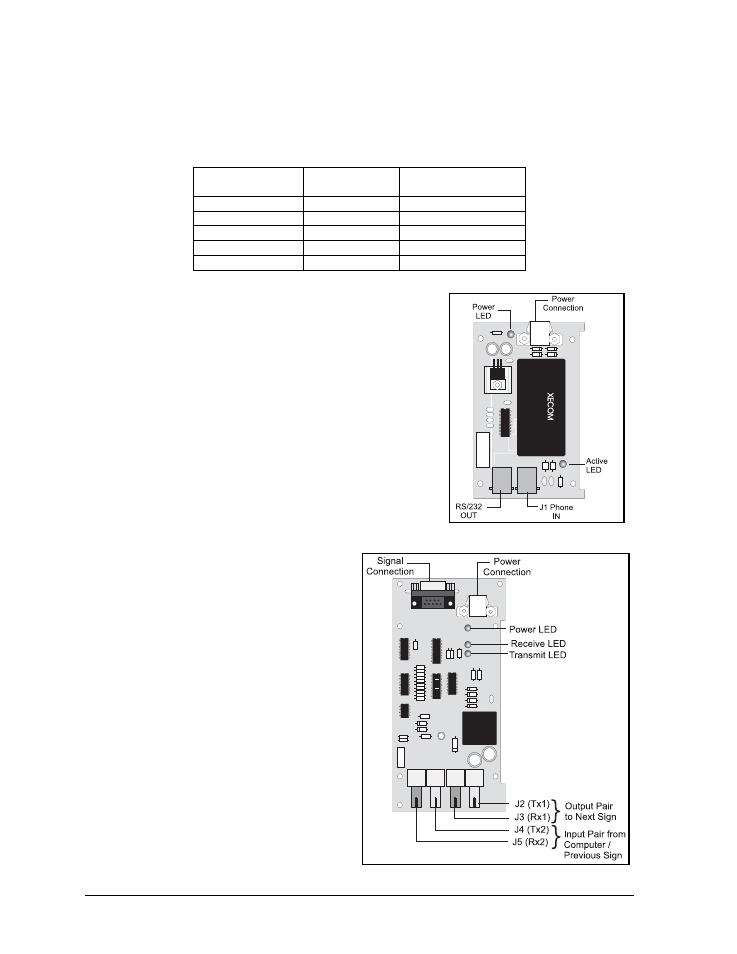
Figure 23: Modem
Modem
If a modem was included with the display, it is located inside
the display next to the controller board.
1. To replace a modem, first disconnect the power and
signal connections (refer to Figure 23 for the location of
the power jack).
2. The modem is held in place with four screws. Remove
the screws and lift the modem out of the display.
3. Attach the new modem using the same four screws
removed in step 2, above.
The modem module has two LEDs. The Power LED should
remain lit while power is applied to the modem. The Active
LED will light when the modem is in the process of
communicating.
Figure 24: Fiber Optic Board
A modem system requires jumpers to be set
on the controller board. Refer to the
Controller section for the jumper settings.
Fiber Board
The fiber module has three LEDs. The power
LED (DS1) should remain lit while power is
applied to the module. The receive LED
(DS2) will light when the display fiber board
is accepting signal from the computer fiber
board. The transmit LED (DS3) will light
when the display fiber board is sending to the
computer fiber board. In addition, the fiber
module has two input fiber connectors, which
the computer or the previous display
connects to, and two output fiber connectors
that connect to the next display. The fiber
board connects to the controller board with a
small DB9 adapter and straight through RJ11
cable.
Maintenance &
4-6
Troubleshooting