Transformer & rfi filter, Transformer, Rfi filter – Daktronics AF-3065-34-RGB User Manual
Page 29: Controller, Transformer & rfi filter -3, Controller -3, Figure 21: controller component layout -3
Transformer & RFI Filter
L
R
EMEMBER
: D
ISCONNECT POWER BEFORE SERVICING ANY INTERNAL COMPONENTS
.
Transformer
The transformer is located in the upper portion of the power termination box (T1 in Drawing
A-149554). To replace the transformer, first disconnect all the wires attached to it. Turn off
power to the display before removing the wires. Then release the hardware securing it to the
inside of the enclosure. Position the new transformer in its place, and tighten it down. Re-
connect all the wires using the display’s schematic as a reference.
RFI Filter
The RFI electrical filters are mounted above and to the side of the power termination box (Z1
and Z2 in Drawing A-149554). Like the transformer, the filters can be replaced by first
removing all connecting wires, then releasing the attachment hardware. Install the new filter
using the display’s schematic as a wiring reference.
Controller
The controller sends data to the modules. Refer to the signal summary in Section 4.2 for more
information and to the component location drawings for the position of the controller board.
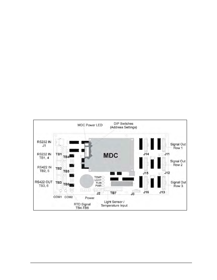
Figure 21 illustrates a typical controller.
Figure 21: Controller Component Layout
“DIP” switches are located on the controller’s MDC. The DIP switches set the hardware address,
which the software uses to identify that particular display. When replacing a controller board, be
sure to set the DIP switches in the same address configuration as the defective controller.
Note: Setting the DIP switches to address 0 (turn all the switches to OFF by flipping them toward
the printed switch numbers) can activate a test mode. The display’s power must be turned off and
then turned back on to run the test mode.
Maintenance &
4-3
Troubleshooting