Rs-422 communication, Figure 12: rs-422 communication layout, 2 rs-422 communication – Daktronics AF-3400-12-RGB User Manual
Page 23
4.2 RS-422
Communication
If the communication system is RS-422, look for:
• a signal converter near the computer.
• wires from the signal converter connecting to an enclosure at the display.
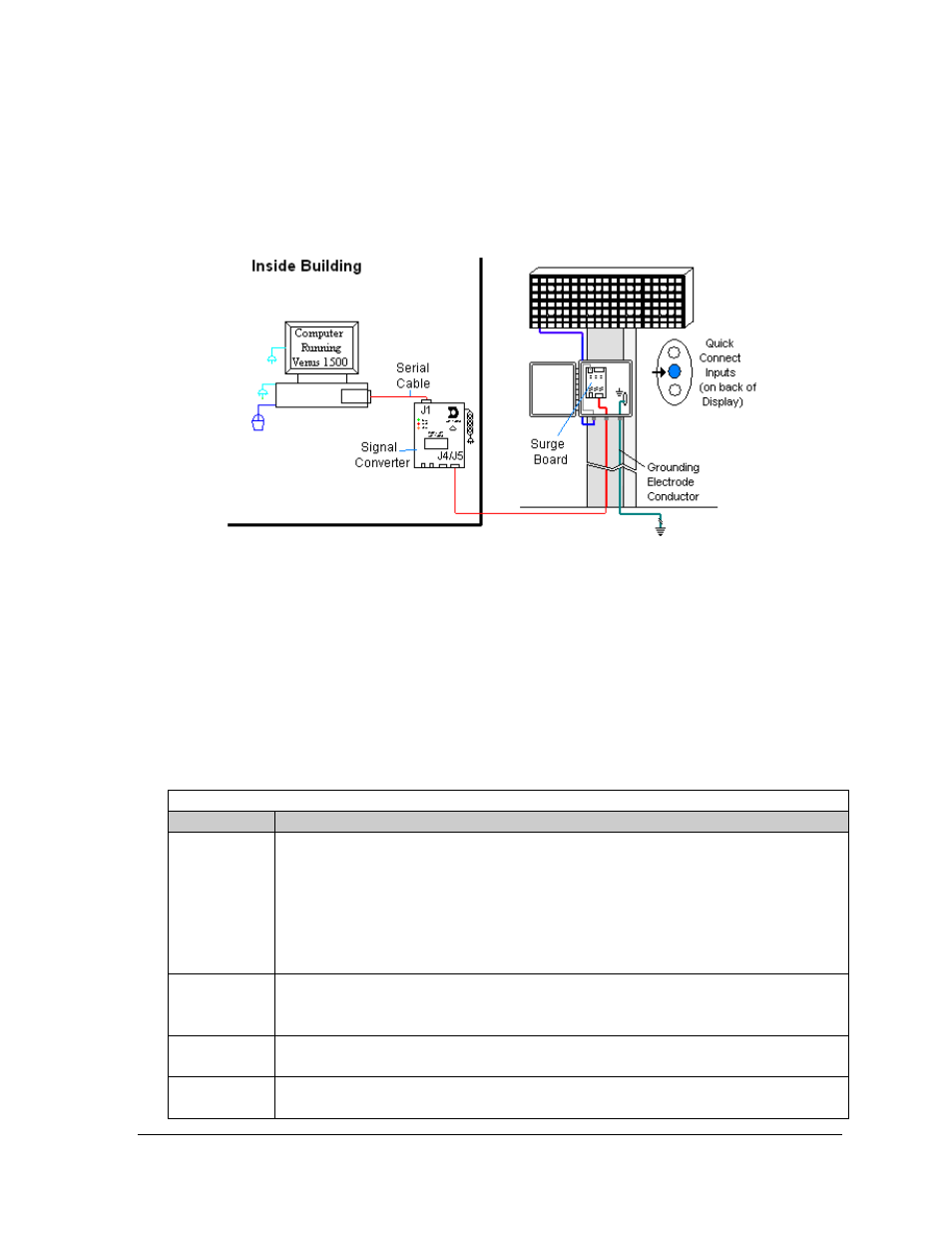
Figure 12: RS-422 Communication Layout
Connections
• Computer to signal converter − six-foot serial cable with 9-pin plug connecting to
computer port or USB adaptor and 25-pin plug connecting to the signal converter at J1,
RS232 IN.
• Signal converter plugged into a 120 volt AC outlet.
• Signal converter to surge board at display − four individual wires from green Phoenix
plug at either J4 or J5 run to Phoenix plug on surge board.
• Surge board to display − quick-connect cable from enclosure to the center jack on display
back.
Troubleshooting
Component
Check
Cable
Connections
•
The serial cable connects the computer to the signal converter.
•
All the wires are connected at the signal converter and the surge board. They need
to be making good electrical contact with the metal, no interference.
•
The color sequence of the wires should be the same to both signal converter and
surge board (e.g. black, white, red and black, white, red).
•
The quick-connect cable is connected from the enclosure to the center jack on the
back of the display.
Diagnostic
LEDs
•
The green LED on the signal converter should be on when plugged into power.
•
The red transmit and amber receive LEDs will flash when sending and receiving
signal from the display; otherwise they are off.
Display Power
•
The display is either running a message or showing a single pixel flashing in the
bottom right corner of the display when power is on.
Software
•
The software and the display are set for the same network address.
•
Refer to the software manual for other possible conditions.
Signal Overview
17