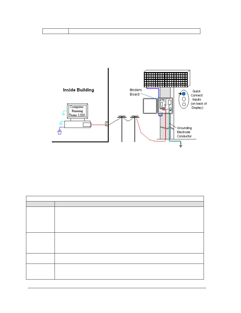
Modem communication, Figure 19: modem communication layout, 9 modem communication – Daktronics AF-3400-12-RGB User Manual
Page 30
• Refer to the software manual for other possible conditions.
4.9 Modem
Communication
If the communication system works with a modem, look for:
• a modem (internal or external) at the computer that connects to a phone jack.
• a phone line connects to the display enclosure.
Figure 19: Modem Communication Layout
Connections
•
Computer modem (internal or external) to phone jack on wall − phone cable plugs into
both.
•
Phone jack to modem at display − signal runs on local telephone lines.
•
Modem board in enclosure to display − quick-connect cable from enclosure to top jack
on display back.
Troubleshooting
Components Check
Cable
Connections
•
The phone line is connected from the modem at the computer to the phone jack.
•
The two phone wires are connected at the modem board (Wire color is determined by
the phone company.)
•
The wires are making good electrical contact with the metal, no interference.
•
The cable is connected from the enclosure to the top jack on the display back.
Diagnostic
LEDs
•
The modem in the enclosure has the green LED on, indicating power.
•
The bottom red LED (carrier detect) is on when the modems are connected.
•
Transmit and receive LEDs flash when sending and receiving signal over the telephone
line; otherwise, they are off.
Display Power
•
The display is either running a message or showing a single pixel flashing in the bottom
right corner of the display when power is on.
Software
•
The software and the display are configured for dial-up communication and the phone
number is correct.
•
Refer to the software manual for other possible conditions.
Signal Overview
24