Jumper settings, Chapter 2 jumper settings – DFI PIC-H61 User Manual
Page 14
www.dfi .com
14
Chapter 2 Hardware Installation
Chapter 2
Jumper Settings
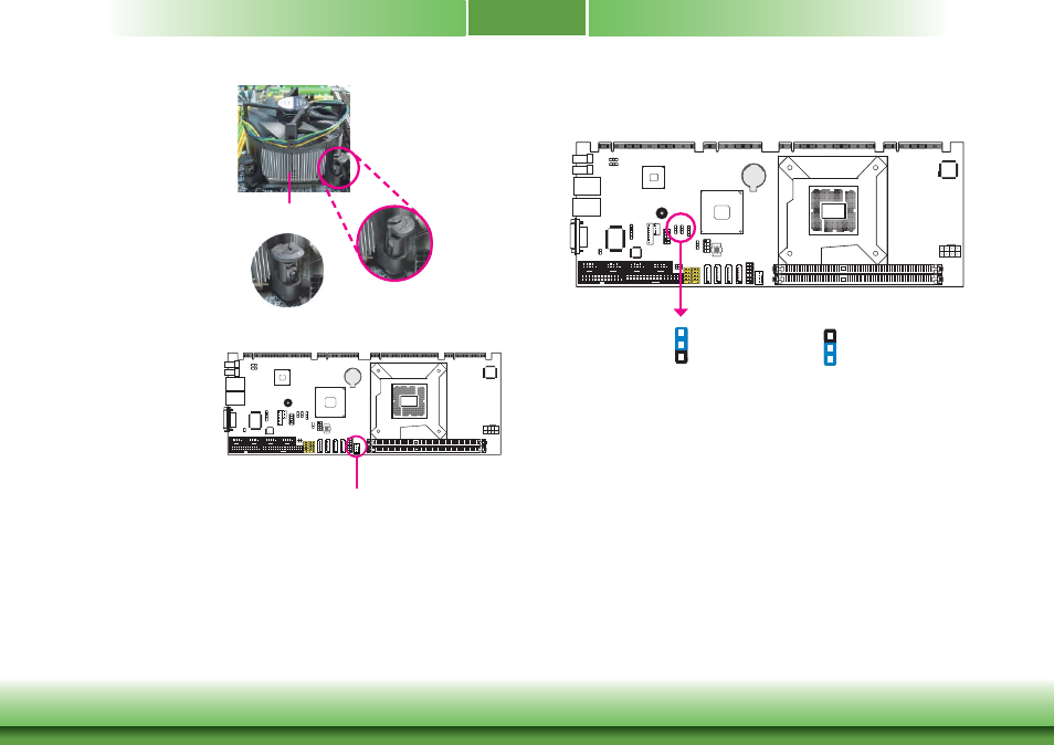
Clear CMOS
If you encounter the following,
a) CMOS data becomes corrupted.
b) You forgot the supervisor or user password.
you can reconfigure the system with the default values stored in the ROM BIOS.
To load the default values stored in the ROM BIOS, please follow the steps below.
1. Power-off the system and unplug the power cord.
2. Set JP4 pins 2 and 3 to On. Wait for a few seconds and set JP4 back to its default setting,
pins 1 and 2 On.
3. Now plug the power cord and power-on the system.
JP4
2-3 On: Clear CMOS
1-2 On: Normal
(default)
1
3
2
1
3
2
4. Rotate each push-pin ac-
cording to the direction of
the arrow shown on top of
the pin.
Push down two pushpins
that are diagonally across
the heat sink. Perform the
same procedure for the
other two push-pins.
Heat sink
“Locked” position of
push-pin
5. Connect the CPU fan’s
cable to the CPU fan
connector on the system
board.
“Unlocked” position
of push-pin
CPU fan connector