Chapter 2 – DFI PIC-H61 User Manual
Page 22
www.dfi .com
22
Chapter 2 Hardware Installation
Chapter 2
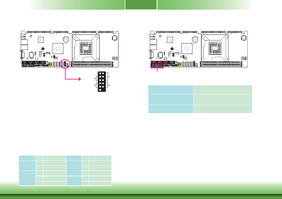
Front Panel Connector
HDD-LED - HDD LED
This LED will light when the hard drive is being accessed.
RESET SW - Reset Switch
This switch allows you to reboot without having to power off the system.
PWR-BTN - Power Switch
This switch is used to power on or off the system.
PWR-LED - Power/Standby LED
When the system’s power is on, this LED will light. When the system is in the S1 (POS - Power
On Suspend) state, it will blink every second. When the system is in the S3 (STR - Suspend To
RAM) state, it will blink every 4 seconds.
HDD-LED
RESET-SW
PWR-LED
PWR-BTN
12
11
2
1
Pin Pin Assignment
Pin Pin Assignment
HDD-LED
3
HDD Power
PWR-LED
2
LED Power
5
Signal
4
LED Power
RESET SW
7
Ground
6
Signal
9
RST Signal
PWR-BTN
8
Ground
11 N.C.
10
Signal
LPT Connector
LPT
The LPT port is for interfacing your PC to a parallel printer. It supports SPP, ECP and EPP.
SPP
(Standard Parallel Port)
Allows normal speed operation but in one
direction only.
ECP
(Extended Capabilities Port)
Allows parallel port to operate in bidirectional
mode and at a speed faster than the SPP’s data
transfer rate.
EPP
(Enhanced Parallel Port)
Allows bidirectional parallel port operation at
maximum speed.