Chapter 2 - hardware installation, System board layout, Hardware installation – DFI CP100-NRM User Manual
Page 16: Intel qm57
Advertising
16
2
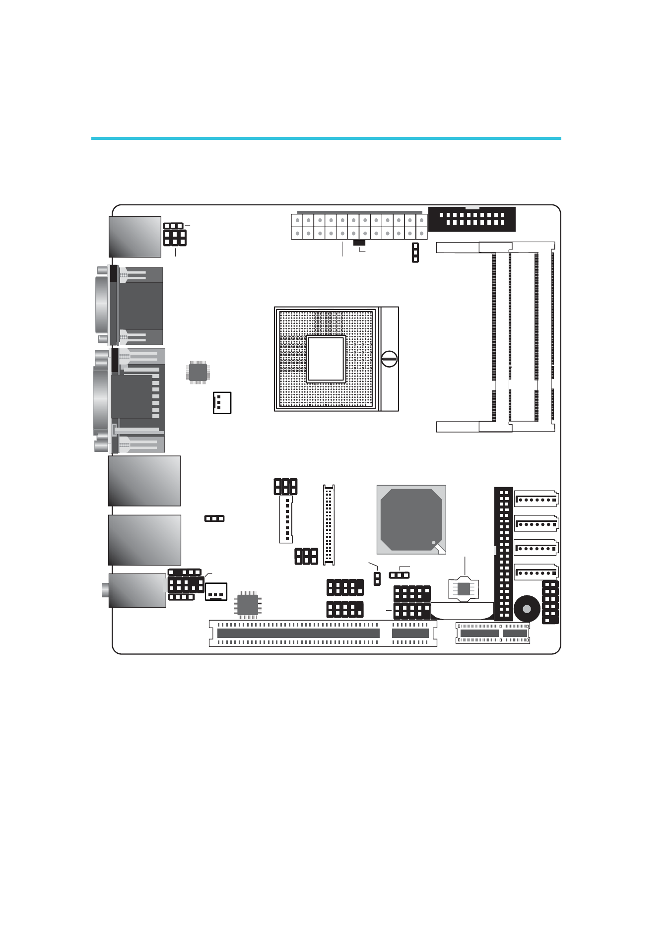
Hardware Installation
System Board Layout
Chapter 2 - Hardware Installation
SATA 0
1
SATA 1
1
SATA 4
1
SATA 5
1
Clear CMOS
(JP5)
1
CPU fan
USB 2-3
1
SPI Flash
BIOS
1
Front audio
1
DIO
1
2
19
COM 2
COM 1
DV
I-I
p
or
t
(DVI
-D
signal
only)
LAN 1 (Intel)
USB 1
USB 0
LAN 2 (Realtek)
USB 9
USB 8
Mic-in
Line-in
Line-out
13
ATX power
12
24
1
1
LCD/Inverter
power
1
Fintek
F81216
USB 0-1, 8-9 power
select (JP2)
Power-on
select (
)
JP6
1
System fan
CD-in
S/PDIF
1
1
IDE
1
1
Front
panel
1
1
Battery
Socket
G
rPGA
988A
DVI-I
VGA
PS/2 power
select (JP1)
COM3
COM4
PCI Express x1
PCI
PS/2 Mouse
PS/2 KB
Chrontel
CH7318C
5
6
1
1
1
2
1
Standby
Power LED
DDR3_2
SODIM
M
DDR3_1
SODIM
M
Panel power
select (
)
JP8
2
5
6
COM3 RS232/485
select (
)
JP11
1
2
5
6
LVDS LCD
panel
1 2
39 40
1
2
9
1
2
9
Chassis
intrusion
USB
4-5
2
Intel
QM57
2
11
COM2 RS232/Power
select (JP4)
Advertising