DFI HR100-CRM User Manual
Page 22
22
2
Hardware Installation
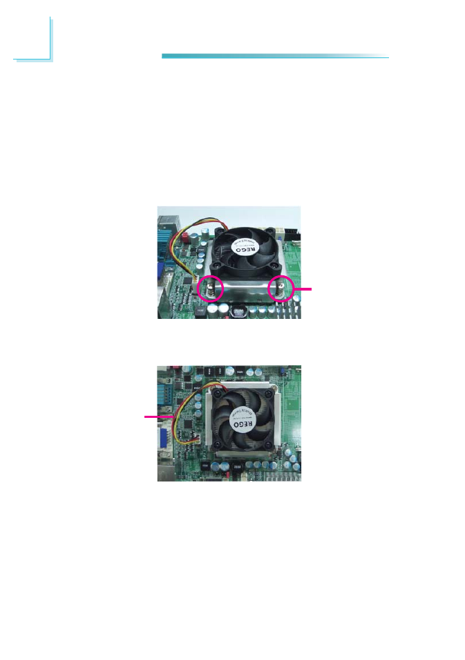
5. Connect the CPU fan’s cable connector to the CPU fan connector on the sys-
tem board.
Mounting
screw
4. Place the fan / heat sink assembly on top of the CPU. The 4 screws around
the heat sink must match the screw holes of the retention module base. We
strongly recommend using this type of fan / heat sink assembly because it
provides adequate cooling to the components of the system board.
Turn each Phillips head screw half way down fi rst to initially stabilize the heat
sink onto the board, then fi nally tighten each screw.
Important:
Do not turn the fi rst screw all the way down followed by the next and so on.
This is to avoid imbalance which might cause cracks or fractures to the CPU
and/or heat sink assembly.
CPU fan cable