B. production switcher, Connection diagram – DNF Controls 4040CL-EVS-PBIO User Manual
Page 7
4040CL-EVS-PBIO, 300 Clip Fast Access System, EVS DDRs
Page 7 of 26
b. PRODUCTION
SWITCHER
1)
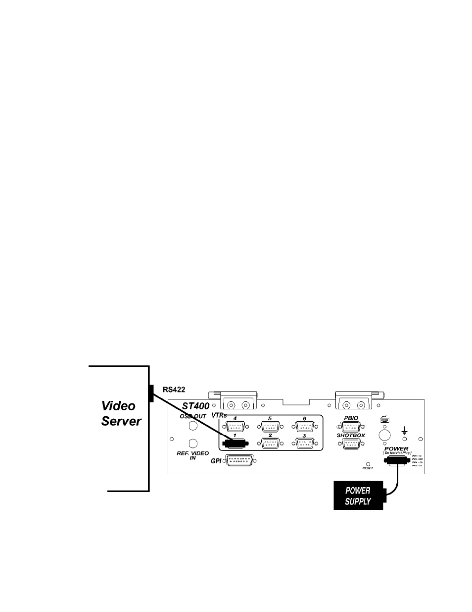
Plug one end of a 9-conductor, RS422 serial cable into the “PBIO” connector on
the rear of the ST400. Connect the other end of the cable to the Peripheral Bus
Connector on the production switcher.
2)
Refer to “SETUP MENU,” Section 15 to set VTR1, VTR2, VTR3, VTR4,
VTR5, & VTR6 Pbus Device Addresses, PBIO parity to match the Production
Switcher, and Production Switcher type.
The Pbus baud rate must be set to “38400” on the Production Switcher.
3)
Configure the production switcher:
On the production switcher -
Enable the Peripheral Bus.
Enable the Peripheral Device Addresses assigned to the ST400.
Enable the appropriate Learn/Recall levels.
Enable the Timeline or Recall Trigger function.
Installation is complete.
CONNECTION DIAGRAM