Installing the interface relay harness – DR Power 6000-Watt Generator User Manual
Page 17
CALL
TOLL
FREE
1-800-DR-OWNER 13
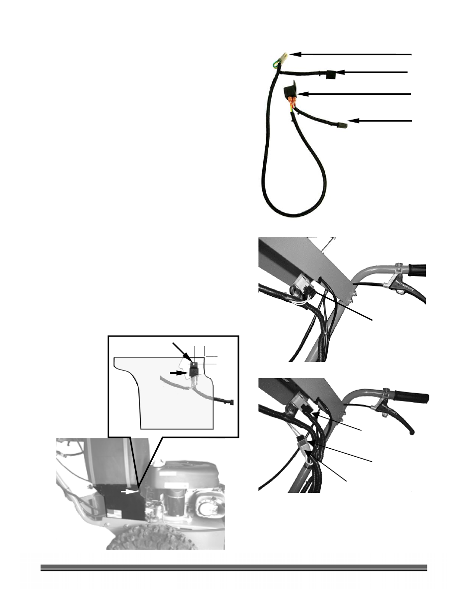
Figure 13
Installing the Interface Relay Harness
NOTE: See page 17 for the AT-3 Lock-In/Out model ATM.
Tools Needed:
•
3/8" Open End Wrench
•
Phillips Screw Driver
•
Electric Drill
•
3/16" Drill Bit
•
Tape Measure
1. Examine the Wire Harness and identify the
connections as shown in Figure 12.
2. Locate the Blade Engagement connection
beneath the Handlebar Control Panel
(Figure 13) and remove the existing
connector from the Blade Engagement
Switch.
3. Insert
Connector
B into the Blade
Engagement Switch (Figure 14).
4. Plug the Original Wire Harness Connector
into the A Connector of the new harness.
5. Locate and drill a 3/16" hole in the Right
Side Gas Tank Support, if not already there
(Figure 15).
Figure 12
Figure 14
Wire Harness Connections
Original Upper Connection
Existing Blade
Engagement
Connection
New
Connector
B
Original
Connector
New
Connector
A
Right Side Gas
Tank Support
3/16" Hole
1"
1"
Figure 15
Relay Mounted
Vertical
Mounting
Screw
To original Wire Harness PTO Connector
A
PTO Switch (Blade Engagement)
B
UPPER
END
Interface Relay
C
To Generator
D
LOWER
END