DR Power 6000-Watt Generator User Manual
Page 21
CALL
TOLL
FREE
1-800-DR-OWNER 17
Installing the Interface Relay Harness on the AT3 model
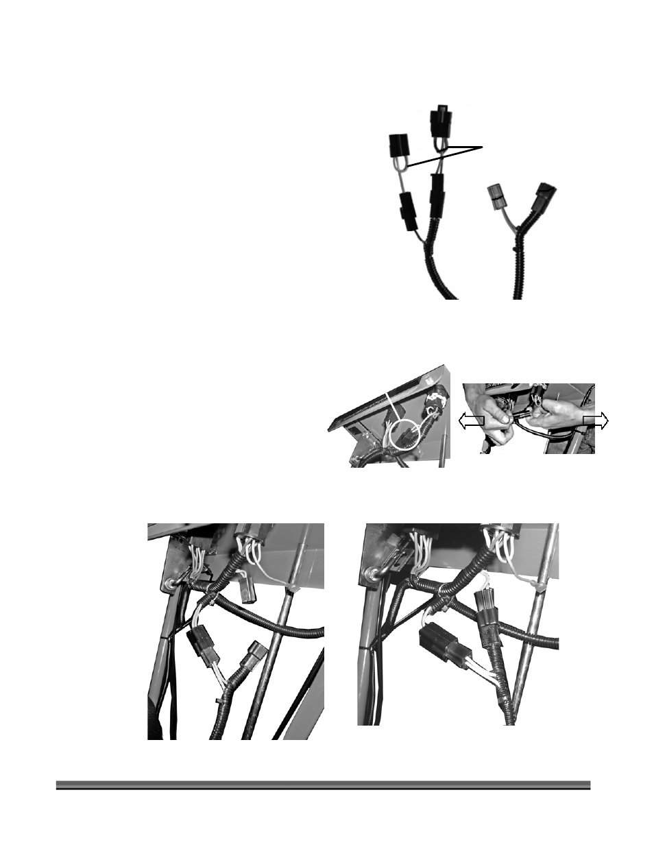
1. Remove the two (2) Extensions (Figure 27)
from the Upper End of the Generator Wire
Harness.
2. Locate the Operator Presence connection
beneath the Control Panel (Figure 28) and
separate the connectors by grasping the wires
on each side of the connector and pulling in
opposite directions as shown.
NOTE: The Generator Connectors are male and
female and will only connect to the ATM
Harness one way.
3. Connect the Generator Wire Harness to the
ATM Harness as shown in Figure 29.
4. Locate and drill a 3/16" hole in the Right Side
Gas Tank Support, if not already there. Refer to
page 13, step 5 for instructions and a list of
required tools.
5. Run the lower end of the new Interface Relay
Harness, with the Relay attached, down along
the Right Handlebar and in back of the Right
Tank Support, and mount the Relay. Refer to
steps 6 through 12 on page 14 for the routing,
mounting of the Relay and connection of the
Harness to the Generator.
6. The Harness installation is now complete. If
you are installing a Maintenance Meter, refer to
page 15.
Figure 29
Figure 28
Figure 27
Extensions
Male Female
Extensions
Removed
Upper End of Generator Wire Harness
Operator Presence
Connection