DR Power 6000-Watt Generator User Manual
Page 18
14 DR
®
GENERATOR ATTACHMENT
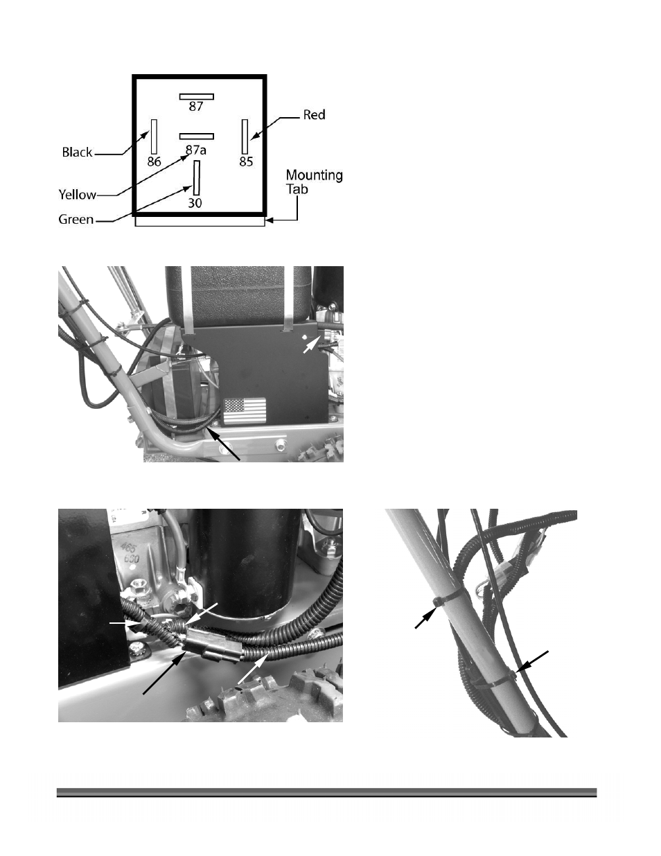
6. Refer
to
Figure 16 for the proper relay
color code connections in the event your
relay should become disconnected.
7. Run the lower end of the new Interface
Relay Harness, with the Relay attached,
down along the handlebar and in back of
the Right Tank Support (Figure 17).
8. Mount the Interface Relay vertically
against the inside of the Tank Support
(Figure 15 on page 13) using the Screw
and Locking Nut supplied.
9. Plug the Connector D (Figure 12 on page
13), from the Relay, into the Generator
Harness (Figure 18).
10. Secure the new wire harness to the
existing ATM harness as shown using a
Cable Tie provided (Figure 18).
11. Secure the upper portion of the Wire
Harness to the handlebar frame using the
plastic Cable Ties provided (Figure 19).
12. Cut off excess Cable Ties. Your
installation is now complete.
Figure 16
Figure 18
Figure 19
ATM Harness
Cable Tie
Generator
Harness
Figure 17
Connector
D
from Relay
Right Tank Support
Interface Relay
behind Support
Interface Relay Harness
Cable Tie
Cable Tie
Right Tank
Support