DR Power RapidFire 6 HP Subaru (July 2012 - Aug 2013) User Manual
Page 14
14
DR
®
RAPIDFIRE™ LOG SPLITTER
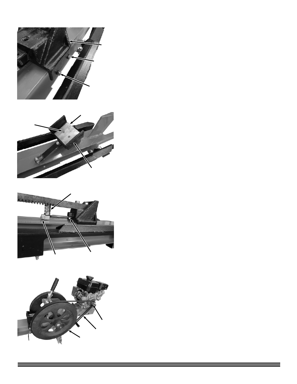
4. Remove the Spring retainer Hardware on both sides of the Ram using two
7/16" Wrenches (Figure 20).
5. Remove the Locknut and Bearing (on the inside) from the Bearing Bolt on
both sides of the Ram using two 9/16" Wrenches. The Bolts remain in place
for now.
6. Lift the Rack up and slide the Ram under it towards the back of the machine
locating it between the Log Cradle and the Belt Guard so the Bearing Bolts
can be removed from the Ram.
7. Lift the Ram from the Frame and turn it over to gain access to the Wear Plate
Hardware (Figure 21).
8. Remove the two Screws that secure the Wear Plate using a Philips Head
Screwdriver and remove the Wear Plate.
9. Position the new Wear Plate making sure it is not sticking out on either side
of the Ram. Add Thread-Locking Fluid to the threads of the two Screws and
secure the Wear Plate with the Screws using a Philips Head Screwdriver.
10. Reassemble in the reverse order.
Aligning the Carriage Spring Roller (When it is noticeably pushed to
one side)
An adjustment of the Carriage Spring Roller is required if the measurement from
the center of the Roller to the edge of the Frame on both sides is not the same.
Tools and Supplies needed:
1/2" Wrench
Tape Measure
1. Remove the Return Springs as described in step 1 of “Greasing The Rack
and Pinion” on page 12 (Figure 15).
2. Pull the Carriage out approximately half way and loosen the Roller Arm Bolt
with a 1/2" Wrench (Figure 22).
3. Align the Roller to be equal distance from each side of the Frame edge using
a Tape Measure.
Note: Adjust the Compression Spring if needed so it is in the center of the Rack
Teeth.
4. Tighten the Roller arm Bolt.
5. Install the Springs and remove the string.
Replacing the Centrifugal Clutch (If slipping excessively)
Tools and Supplies needed:
1/2" Wrench
Dead Blow Hammer
1. Remove Belt Guard as described in “Changing and Adjusting Belt(s)” (page
16).
2. Remove the Belt(s) by rolling them off the Flywheels as you slowly rotate the
Flywheels (Figure 23).
Flywheel
Figure 23
Belts
Clutch
Bearing
Hardware
Figure 20
Spring
Retainer
Hardware
Ram
Wear Plate
Figure 21
Countersunk
Screws
Ram
Figure 22
Carriage
Spring Roller
Roller Arm Bolt
Compression Spring