Changing and adjusting the belt(s) – DR Power RapidFire 6 HP Subaru (July 2012 - Aug 2013) User Manual
Page 16
16
DR
®
RAPIDFIRE™ LOG SPLITTER
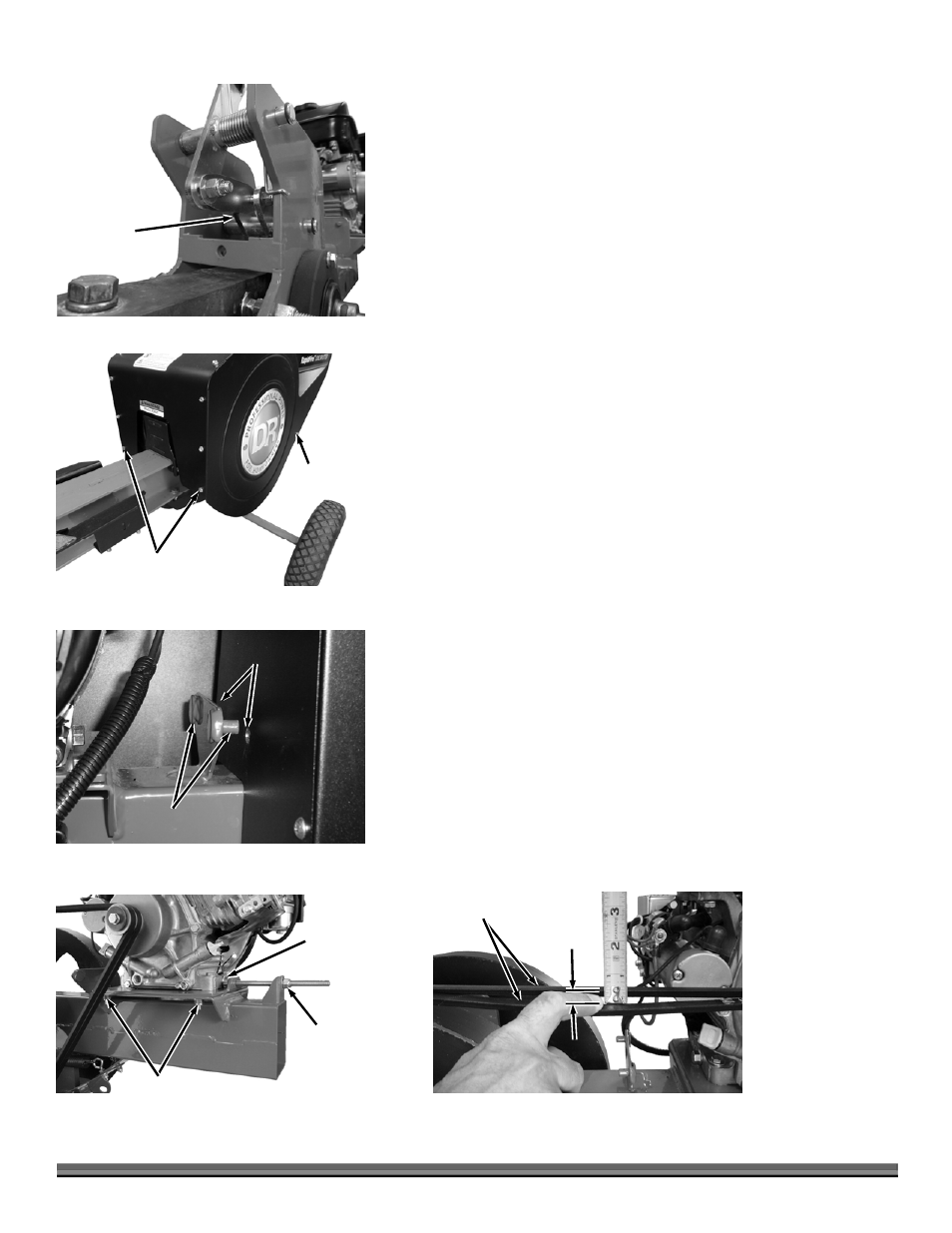
7. Position the linkage assembly into the Frame in the correct orientation
(Figure 28) and install the Pivot Pins and Retaining Rings.
8. Assemble the Flywheels, Belts and Belt Cover in the reverse order of the
steps above.
Changing and Adjusting the Belt(s)
Tools and Supplies needed:
Two 7/16" Wrenches
1/2" Wrench
Two 9/16" Wrenches
1. Remove one Bolt and Locknut on the left side of the Belt Guard with two
7/16" Wrenches (Figure 29).
2. Remove the two lower sets of Bolts and Locknuts at the front of the Belt
Guard with two 7/16" Wrenches.
3. Move the Belt Guard forward and lift it off the alignment pins to remove it
from the machine (Figure 30).
Note: It will help to have someone position the Operator Handle forward to aid in
removal and installation of the Belt Guard.
4. Loosen the four Locknuts that secure the Engine Mounting plate using a
1/2" Wrench (Figure 31).
5. Hold the Tensioner Bolt head with a 9/16" Wrench and loosen the Tensioner
Nut with a 9/16" Wrench until the Engine can be moved forward enough to
remove the Belt(s).
6. Install new Belt(s) onto the Clutch and Flywheel.
7. Adjust the Belt Tensioner by holding the Bolt head with one 9/16" Wrench
while turning the Locknut with another 9/16" Wrench until there is 1/2" of
slack in the Belt(s) (Figure 32).
Note: The Belt on the Pro model Splitter should have between 3/4" to 1" of slack
for proper adjustment.
8. Tighten the Engine Plate Nuts and install the Belt Guard.
Front
Hardware
Figure 29
Side
Hardware
Alignment
Pins
Figure 30
Alignment
Holes
Front of
Belt Cover
Adjuster
Nut
Figure 31
Adjuster
Bolt
Engine Plate Nuts
Belts
Figure 32
Approx.
1/2"
Figure 28
Linkage
Orientation